


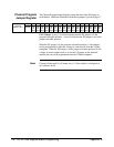
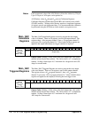
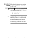

Notes Each incremental value of the A24 Window offsets the window by 32 bytes.
Up to 512 bytes of A24 space can be pointed to.
A24 Window values 8
16
through F
16
point to Calibration Registers.
Calibration Registers 00100
16
through 001BE
16
are located in non-volatile
(FLASH) memory. Writing to this memory requires a complicated sequence
of register accesses not documented here. It is recommended that calibration
be performed using the SCPI driver for the module, not register access.
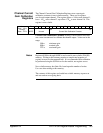
Main_DAC
Immediate
Registers
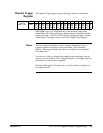
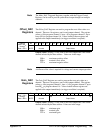
The Main_DAC Immediate Registers are used to program the next output
value on a channel. There are 16 registers, one for each output channel. The
register at base + 40
16
programs channel 1, base + 42
16
programs channel 2,
up to base +5E
16
to program channel 16. Values loaded in these registers are
applied to the output immediately (no trigger condition is required).
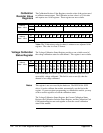
Address
Base + 40
16
through
Base + 5E
16
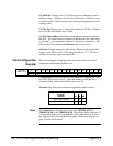
Bit 15 14 13 12 11 10 09 08 07 06 05 04 03 02 01 00
WRITE
Output Value
Output Value: Writing a 16-bit value to this field outputs the value on the
channel selected by the base address. The 16-bit value is a 2’s complement
number. Scaling is based upon 16 V maximum for voltage mode and .020
Amps for current mode.
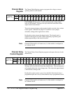
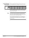
Main_DAC
Triggered Registers
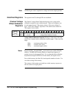
The Main_DAC Triggered Registers are used to program the next output
value on a channel. There are 16 registers, one for each output channel.
The register at base + 60
16
programs channel 1, base + 62
16
programs
channel 2, up to base +7E
16
to program channel 16. Values loaded in these
registers are applied to the output(s) following the next trigger event.
Address
Base + 60
16
through
Base + 7E
16
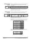
Bit 15 14 13 12 11 10 09 08 07 06 05 04 03 02 01 00
WRITE Output Value
Output Value: Writing a 16-bit value to this field outputs the value on the
channel selected by the base address. The 16-bit value is a 2’s complement
number. Scaling is based upon 16 V maximum for voltage mode and
.020 Amps for current mode.
138 HP E1418A Register-Based Programming Appendix B