


Installing
Isolated/Non-Isolated
Plug-on Modules
Use this procedure to install the isolated plug-on kit (HP E1523A) or to
change the channel isolation configuration.
CAUTION Almost all electrical components can be damaged by electrostatic discharge
(ESD) during handling. Component damage can occur at electrostatic
discharge voltages as low as 50 volts. Disassemble and reconfigure only in a
static free work area. Minimize handling of assemblies and components. Keep
all assemblies and replacement parts in the original static free packaging.
These procedures should be performed by qualified service personnel at
approved static safe workstations.
Tools Needed – T10 Torx Driver (one is provided with the kit)
– Static Safe Workstation
– Static Wrist Strap
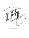
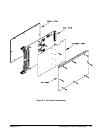
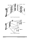
Procedure Refer to Figures E-1 and E-2 during these procedures
1. Remove the top cover.
2. Remove the screw holding the sheet-metal spacer (Figure E-1) or
expansion board (Figure E-2). Remove the spacer or expansion
board.
3. Refer to Figure E-3 for the locations of the isolated/non-isolated
plug-on modules. Each channel must have a plug-on module.
Remove the screw securing the plug-on module(s).
4. Use Figure E-4 to identify isolated or non-isolated plug-on modules.
Install the new plug-on module as shown in Figure E-4. Note the
locator pin on the main board or expansion board that ensures correct
orientation. Replace the screw in the plug-on module.
5. Repeat steps 3 and 4 for each channel.
6. Reinstall the sheet metal spacer or expansion board (a complete
procedure for the expansion board is given earlier in this chapter).
7. Replace the top cover.
8. Perform the adjustment procedures on the module. See Appendix D,
beginning on page 154.
171 Configuration and Disassembly Appendix E