


Calibration Constants and Non-Volatile Memory
The accuracy of a channel output depends upon a number of calibration
constants. Calibration constants are stored in two locations within the
module; in non-volatile memory and in RAM. The constants in RAM are
used by the module to adjust all outputs.
When the module is used with the SCPI driver, the RAM constants are
loaded from the non-volatile memory at power-up. You can adjust the
RAM calibration constants without disturbing the non-volatile memory
constants (creating a temporary calibration).
Non-volatile memory has a finite number of writes. Writing the calibration
constants to non-volatile memory, therefore, reduces the life of this
memory. If you are calibrating the module at 90 day or 1 year intervals,
write the new constants into non-volatile memory. The new constants will
be used following power-up. If you are calibrating the module more
frequently (daily, for example), write the new calibration constants into
RAM, but do not write to non-volatile memory.
The adjustment procedures shown in this appendix demonstrate both
methods of writing calibration constants.
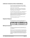
Equipment Required
The following equipment is recommended for calibration and adjustment.
Key specifications are listed to allow for equipment substitutions.
Model Requirements
Digital Multimeter (DMM)
5
1
⁄
2
or 6
1
⁄
2
digit
Voltage measurements to ±16.8 V
Four-wire Resistance measurements
from 50 Ω to 500 Ω
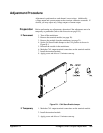
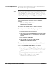
Making Connections
All adjustment can be performed using the CAL output terminals. The
CAL output terminals provide one set of connections for both voltage and
current adjustment.
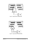
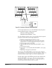
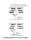
Optionally, you can also perform the adjustment at each channel output (to
include the output relay contacts in the path). Before beginning adjustment
procedures, you must send the
DIAGnostic:CALibration:OUTPut CHANnel
command to set the adjustment point at the channels instead of the CAL
output terminals. Adjustment at each channel output will require individual
connections. You must make a four-wire connections for the adjustment
procedures.
155 Voltage/Current Output Adjustment Appendix D