


11
Chapter_Title
Main Body
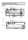
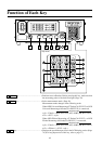
<Front>
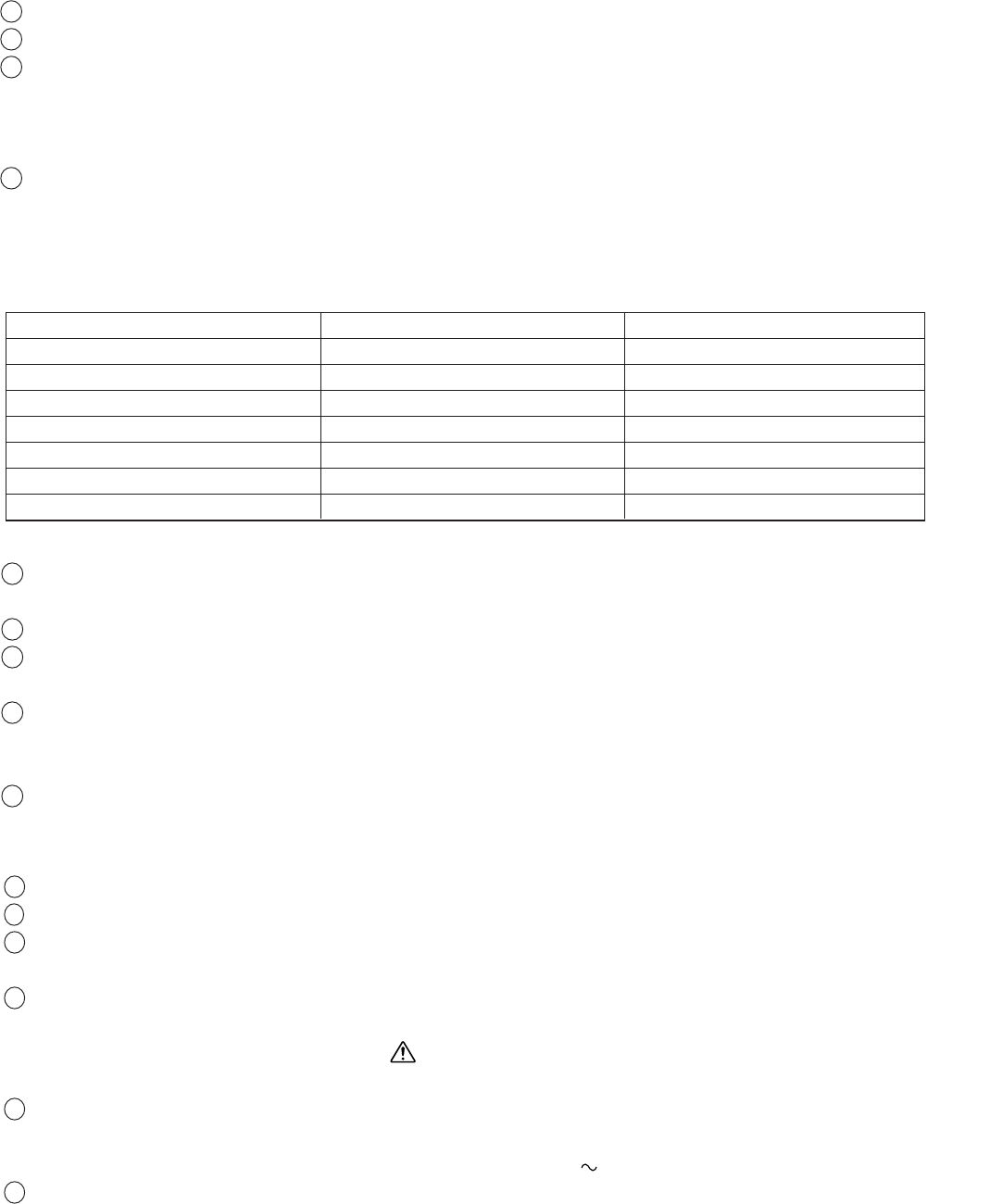
1 POWER switch........................................ • Used to turn ON and OFF the power to the instrument. (Page 29)
2 Digital display section ............................. • Displays the measured values.
3 Analog display section ............................ • Displays the difference (%) between the measured value and the
target color or the difference (%) between measured values.
Measured values are displayed in the case of flicker mode.
• The range for each dot can be set between 0.1 and 99%. (Page 69)
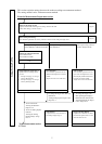
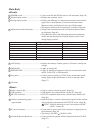
4 Measurement mode indications ............... • Displays the measurement mode in which the measured values
are displayed. (Page 40)
• The table below shows the relationship between measurement
modes and data displayed in the digital display section 2 and
analog display section 3.
Measurement mode
2
Digital display
3
Analog display
xyLv mode x, y, Lv ∆x, ∆y, ∆Lv
T∆uvLv mode T, ∆uv, Lv ∆x, ∆y, ∆Lv
Analyzer mode (G reference) R, B, G R/G, B/G, ∆G
Analyzer mode (R reference) R, B, G ∆R, B/G, G/R
u'v'Lv mode u', v', Lv ∆x, ∆y, ∆Lv
Flicker mode** Flicker value Flicker value
XYZ mode XYZ ∆x, ∆y, ∆Lv
**Only when LED Flicker Measuring ø27 Probe or LED Flicker Measuring ø10 Probe is connected.
5 LCD display ............................................ • Displays the memory channel, probe no., ID name, warning and
settings.
6 HOLD LED ............................................. • Lights up during hold.
7 REMOTE LED ........................................ • Lights up when the instrument is ready for communication with
the PC via RS-232C or USB interface.
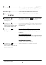
8 Key panel................................................. • Used to select/set probe no., SYNC mode, measurement speed,
analog display range and ID name, as well as entering values.
(Page 17)
9 Tilt stand
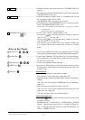
<Rear>
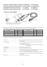
10
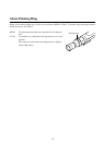
Probe connector [P1] ............................... • Used to connect a measuring probe. (Page 26)
11
USB connector ........................................ • USB interface for communication with the PC. (Page 88)
12
RS-232C connector ................................. • RS-232C compatible interface for communication with the PC.
(Page 86)
13
Vertical synchronizing signal .................. • Input the display’s vertical synchronizing signal into this terminal
input terminal when performing measurement in EXT SYNC mode. (Page 28)
SYNC: Terminal shall tread as class 3 accordance with IEC
610101-1 Annex-H.
14
AC power connector ................................. • Connect the AC power cord to this connector to supply power to
the instrument. (Page 28)
• The rating is 100-240V
, 50-60 Hz, 50VA.
15
4-Probe Expansion Board slot ................. • Used to install the optional 4-Probe Expansion Board (CA-B15).
(Page 27)