71
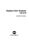
Settings Section
[Setting Procedure]
1
5
3
2
4
1. Press the MODE key to select the measurement mode
for which you want to set the range.
2. Press the key.
The LCD display section will switch to the menu selection screen.
3. Press the key to open the RANGE setting screen.
Each time the key is pressed, the screen will switch in the order
PROBE → SYNC → ID Name input → RANGE → Measurement
Speed → Number of Digits → Calibration Standard→ RS232C Baud
Rate → PROBE.
4. Enter the desired range value.
Use the number-key ( to , ) to enter the value. (The cursor
moves to the right each time a value is entered.)
Each time the
key is pressed, the cursor moves between x, y and
Lv, between G and B/G, R/G or between R and B/G, R/G. (This does
not apply in the case of flicker mode**.)
In this example, the “x, y” range is set to 2.5%, and the “Lv” range is
set to 2.0%.
1 Press the , and then key to set the “x, y” range.
2 Press the key.
The cursor (_) will move to the “Lv” position.
3 Press the , and then key to set the “Lv” range.
5. Press the key.
The ranges will be set.
*To cancel range setting, press the key before pressing the key.
* By default (factory setting), the ranges are set to 10%.
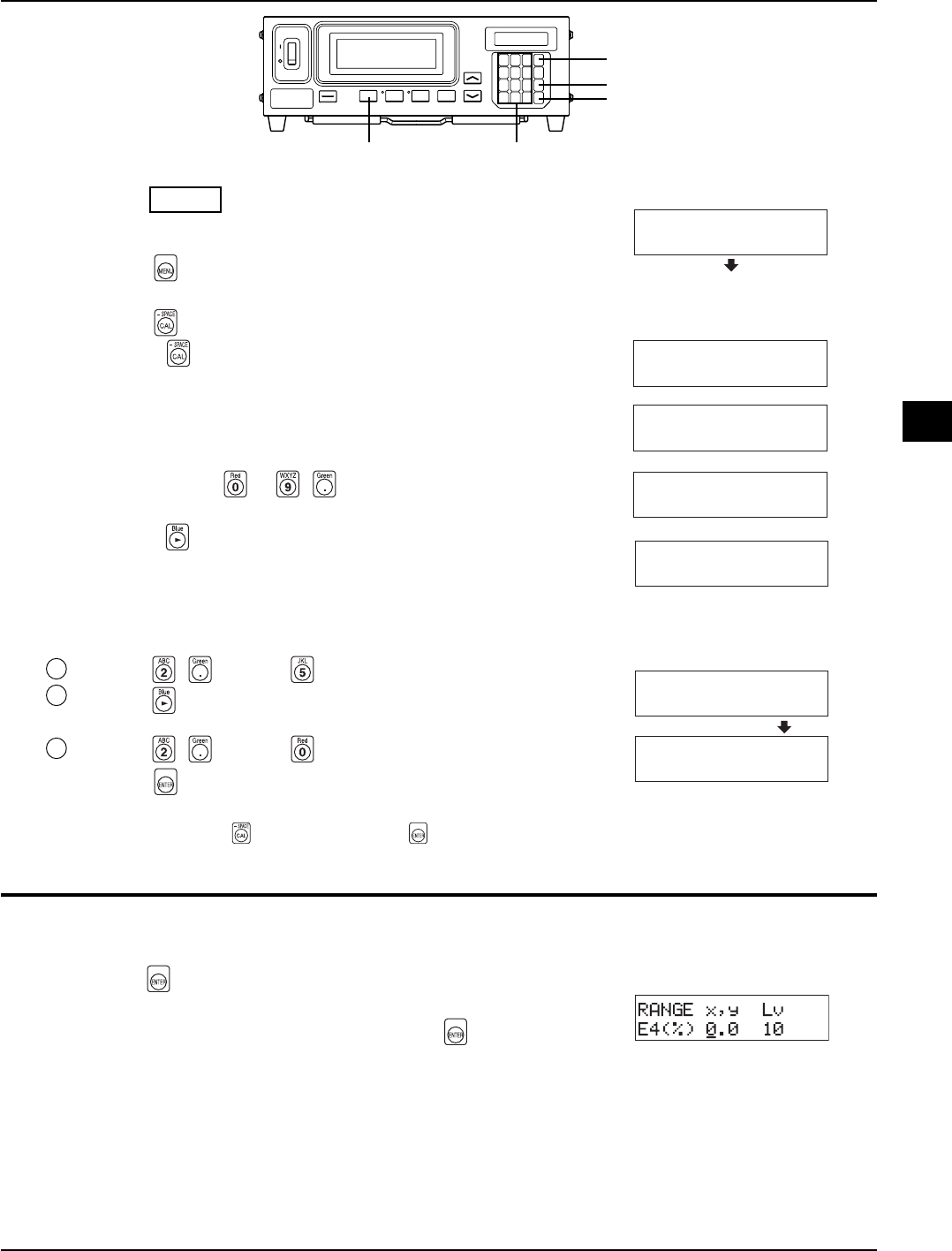
<Error Messages in LCD Display Section>
…
For other error messages, refer to page 103.
● “E4” (after the
key is pressed)
• Cause : 0.0% was entered.
• Action : Enter a correct value and then press the
key. The settable
range is from 0.1 to 99%.
RANGE FMA
(%) 10
RANGE x,y Lv
(%) 2.5 10
_
RANGE x,y Lv
(%) 2.5 2.0
_
RANGE x,y Lv
(%) 10 10
_
RANGE G B/G,R/G
(%) 10 10
_
RANGE R B/R,G/R
(%) 10 10
MENU : SELECT
PUSH SPACE KEY
Menu selection screen
Range setting screen
(For xyLv, T∆uvLv, u'v'Lv
or XYZ mode)
For analyzer mode (G reference)
For analyzer mode (R reference)
For flicker mode**
**Flicker Mode is a function which can be used only when LED Flicker Measuring ø27 Probe(CA-P32/35) or LED Flicker Measuring ø10
Probe(CA-PS32/35) is connected.