


2929
Installation/Connection
SET MAIN PROBE
PROBE ERROR
Turning the Power ON ( | )/OFF (●● )
1. Turning the Power ON ( |
)/OFF
(
●●
)
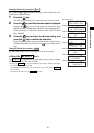
Before setting the POWER switch to ON ( | ), prepare the following.
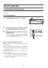
1. Connect a measuring probe to the probe connector [P1]. (Page 26)
• To synchronize measurement with the ... 1
Input the vertical synchronizing signal that is used for the display.
display’s vertical synchronizing signal (Page 28)
(EXT is selected as the SYNC mode)
• To perform measurement .......................
1
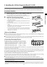
Install the 4-Probe Expansion Board (option) in the
with two or more measuring probes
in
strument. (Page 27)
2 Connect necessary number of probes to the probe connec-
tors [P2] to [P5]. (Pages 26 and 27)
• To communicate with the PC .................
1
Connect the instrument’s RS-232C connector to the PC. (Page 86)
via RS-232C
• To communicate with the PC via USB...
1
Connect the instrument’s USB connector to the PC. (Page 88)
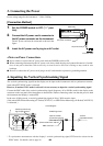
2. Connect the AC power cord to an AC outlet. (Page 28)
[Turning the Power ON ( | )]
Set the POWER switch to ON ( | ).
If the instrument is connected to exter-
nal equipment, set the instrument’s
POWER switch to ON ( | ) first, then
turn ON ( | ) the power to the external
equipment.
[Turning the Power OFF (●●)]
If the instrument is connected to external equipment, turn OFF (●●) the power to the external equipment
first, then set the instrument’s POWER switch to OFF (●●).
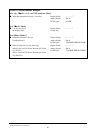
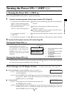
<Error Messages in LCD Display Section>
…
For other error messages, refer to page 101.
● “SET MAIN PROBE” (After the POWER switch is set to ON ( | ))
• Cause 1 : The measuring probe is not connected to the probe con-
nector [P1] properly.
• Action 1: Set the POWER switch to OFF (●●), then connect the measuring probe to the probe connector
[P1] properly. (Before connecting/disconnecting the measuring probe, make sure that the
POWER switch is set to OFF (●●).)
● “PROBE ERROR”
• Cause 1 : A measuring probe was connected or disconnected while
the POWER switch was ON ( | ).
• Action 1: Set the POWER switch to OFF (●●) first, connect necessary measuring probes, then set the
POWER switch to ON ( | ). (Before connecting/disconnecting the measuring probe, make sure
that the POWER switch is set to OFF (●●).)
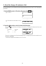
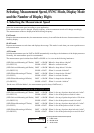
PROBE [P1]
NO.XXXXXXXX A
DARKEN PROBE
PUSH 0-CAL KEY
Probe serial no.
“C ”:
LED Universal Measuring ø27 Probe
(CA-PU32/35)
“D ”:
LED Universal Measuring ø10 Probe
(CA-PSU32/35)
“ A ” :
LED Flicker Measuring ø27 Probe
(CA-P32/35)
“ B ” :
LED Flicker Measuring ø10 Probe
(CA-PS32/35)