


1313
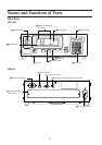
Installation/Connection
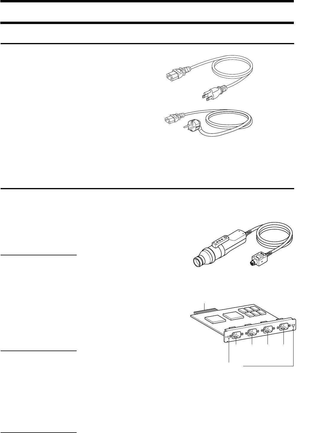
(For 100-120 V)
(For 200-240 V)
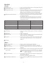
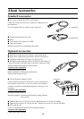
About Accessories
Standard Accessories
● AC power cord (For 100-120V or 200-240 V)
Connect this cord to the AC power connector to supply power to
the instrument.
For a description of how to connect, refer to page 28.
● Measuring probe(with a lens cap)
● Hood
● Color analyzer PC software CA-SDK
● Instruction manual
Read this manual before operating the instrument.
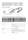
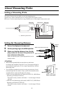
Optional Accessories
● LED Universal Measuring ø27 Probe CA-PU32/CA-PU35
● LED Universal Measuring ø10 Probe CA-PSU32/CA-PSU35
● LED Flicker Measuring ø27 Probe CA-P32/CA-P35
● LED Flicker Measuring ø10 Probe CA-PS32/CA-PS35 (Page 12)
Connect the probes to the main body or the probe connectors on the
4-Probe Expansion Board before measurement.
Location of the explanation
Connecting method: Page 26
Measuring method: Measurement Preparation,
Setting, Measurement sections
[P2]
[P3]
[P4]
[P5]
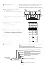
Probe connector
Connector
Grip
● 4-Probe Expansion Board CA-B15
Connect measuring probes to this board, to allow simultaneous
measurement of the colors at up to 5 points on the display’s
surface.It is possible to install Measuring Probes of all types to be
coresident.
Location of the explanation
Installation method: Page 27
Measuring method: Measurement Preparation, Setting, Measure-
ment sections
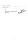
● Standard Hood for CA-210/310 CA-H10 / Small Hood for CA-210/310 CA-HS10
● Standard Lens cap for CA-210/310 CA-H11 / Small Lens cap for CA-210/310 CA-HS11
● USB cable IF-A18
(Used for communication between this instrument and PC.)
Location of the explanation
Connecting method: Page 86