


7
206-4272
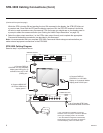
STB-3000 Cabling Connections
This section describes how to connect the STB-3000 to a compatible commercial display panel (LG
Hospitality TV, LG Public Display TV, LG Commercial Monitor, or commercial non-LG TV with MTI support).
Connect the STB to the Display Panel
The following procedure only describes connections that are essential for STB functionality. See Reference
section, “STB-3000 Jack Panels,” for further information on the additional jack panel ports and connectors.
Note: An LG Installer Remote (not supplied) is required to complete this procedure, as well as STB/display
panelcongurationproceduresinthisdocument.IfyouareusinganLGdisplaypanel,astandardLG
InstallerRemoteshouldbesufcient.However,ifyouarenotusinganLGdisplaypaneland/orifyouwish
to take advantage of the STB’s multi-code feature, LG’s STB-dedicated Installer Remote will be required.
See Reference sections, “Installer Remote Typical Key Functions” and “STB Installer Remote,” for further
information.
1. Turn ON the display panel. Before you connect the STB to the display panel, the display panel should
be in a known state. That is, the display panel should be either in a factory default state or custom
congured(initsdefaultmode)withselectedsettings,forexample,theaspectratio,thatyouwishto
use in conjunction with the STB. When you are ready to proceed, leave the display panel turned ON,
and then continue with step 2.
2. Refer to the STB-3000 Cabling diagram on the next page, and complete the following connections:
a)
Make the appropriate Display Control connection between the STB-3000 and the display panel.
• For LG Hospitality TVs: Use the MPI/MTI cable provided to connect DISPLAY CONTROL 2 on the
STB-3000 front jack panel to the MPI port on the rear jack panel of the display.
• For LG Public Display TVs or LG Commercial Monitors: Use the TLM cable provided to connect
DISPLAY CONTROL 1 on the STB-3000 rear jack panel to the RS-232 CONTROL connector on
the rear jack panel of the display.
• For commercial non-LG TVs: Use the MPI/MTI cable provided to connect DISPLAY CONTROL 2 on
the STB-3000 front jack panel to the MTI (typically labeled “DATA”) port on the rear jack panel of the
display.
b)
Use the HDMI cable provided to connect HDMI OUT on the STB-3000 rear jack panel to the HDMI1
input connector on the rear jack panel of the display.
c)
For RF delivered content, connect a 75 ohm coaxial wire from the Antenna/CATV wall jack to
ANTENNA/CABLE IN on the STB-3000 rear jack panel. For IP delivered content, connect an RJ-45
Ethernet (CAT5) cable from the institution’s network to the LAN port on the STB-3000 rear jack panel.
d)
Insert the DC power plug of the AC/DC power adapter provided into the POWER connector on the
rear jack panel of the STB-3000, and then plug the AC/DC adapter into a standard 120V 60 Hz AC
power outlet.
Once power is applied to the STB-3000, the LED on the STB’s front jack panel will light steadily,
indicating that the STB is in standby mode. Also, the display panel will be turned OFF by the STB as
soon as the STB is powered and establishes display control communication with the display.
Note: Once display control communication is established between the STB-3000 and the display
panel, the STB-3000 will be in control of the display panel, and certain resident panel functions, like
panel buttons, will no longer operate.
3. Use the Installer Remote to turn ON the STB/display panel.
(Continued on next page)