


SCREEN SETTING
12
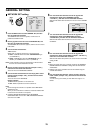
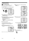
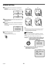
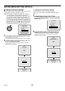
Use the jog dial to set T-2, and then turn the shuttle dial
clockwise.
Repeat this procedure to switch between T-1, T-2, T-3 and T-4.
13
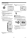
Use the jog dial to move the cursor to 09, and then turn the
shuttle dial clockwise.
“ON” flashes.
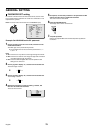
14
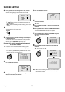
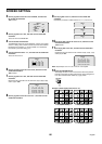
Use the jog dial to set “OFF” , and then turn the shuttle dial
clockwise.
Repeat the above procedure to set cameras 10 (10) through to
16 (16) to “OFF”.
Note: Repeat steps 10 to 12 to set T-3 and T-4 as required.
15
Press the EXIT/OSD button.
The display returns to the normal screen.
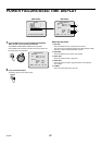
Note:
•
Repeat the above procedure to make the settings for monitor 2.
•
For a 4-screen display, the timer function cannot be used for
automatic switching of screen images.
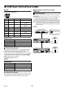
C
MASK settings
If you do not need camera images to be displayed on the monitor
screen, you can hide the images for individual cameras with a gray
pattern.
The DSR-3009P model can display only cameras 01 to 09.
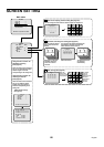
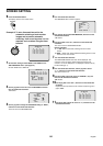
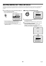
Example 1: To prevent certain camera images from
being monitored for the period of time
set by the timer (TIMER A, B)
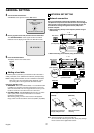
1
Set the timer setting for both TIMER A and TIMER B in the
TIME PERIOD SET menu. (See page 46.)
Set both TIMER A and TIMER B.
<MAIN MONITOR SET>
T-1
<MAIN MONITOR SET>
T-2
<MAIN MONITOR SET>
T-3
<MAIN MONITOR SET>
T-1
IN IN IN IN
01:ON 02:ON 03:ON 04:ON
05:ON 06:ON 07:ON 08:ON
09:OFF 10:OFF 11:OFF 12:OFF
13:OFF 14:OFF 15:OFF 16:OFF
EXIT/OSD
T-1
(6
00 - 12 00)
T-2
(12 00 - 16 00)
T-3
(16
00 - 24 00)
T-4
(24 00 - 6 00)
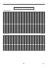
<MASK SET>
T-1
IN IN IN IN
01:OFF 02:OFF 03:OFF 04:OFF
05:OFF 06:OFF 07:OFF 08:OFF
09:OFF 10:OFF 11:OFF 12:OFF
13:OFF 14:OFF 15:OFF 16:OFF
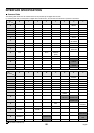
<TIME PERIOD SET>
TIME PERIOD T1 T2 T3 T4
TIME PERIOD A 00:00 00:00 00:00 00:00
TIME PERIOD B 00:00 00:00 00:00 00:00
SELECT TIME PERIOD
SEQUENCE TIME PERIOD A
MASK TIME PERIOD A
MOTION SENSOR TIME PERIOD A
English
85