


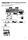
CONNECTIONS
Turn off the power for all components before connecting them.
Be sure to carefully read the Instruction Manual for all equipment being connected to the digital video recorder.
If the connections are incorrect, smoke or operating malfunctions may result.
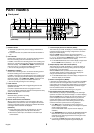
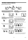
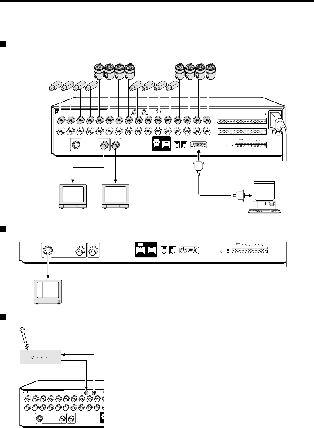
Basic connections (DSR-3016P model)
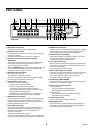
Nine cameras can be connected to the DSR-3009P model.
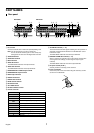
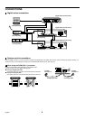
Connecting high image quality (S-VHS) video equipment
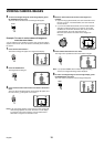
Connecting to an Amplifier
1
SVHS
MAIN MONITOR
A
B
RS485
RS232C
OFF
AC IN~
ALARM IN
SENSOR
ALARM OUT
ON
RS485
C1234567891011 12 13 14 1516
ALL
RESET
TERMINATE
DIGITAL
IN OUT
MON2
MIC IN
2345678 1112
13 14
15 16
CONTROL
109
TV monitor
(sold separately)
VIDEO IN
connector
TV monitor
(sold separately)
S-VIDEO IN
connector
Computer
DO NOT CONNECT TO PHONE LINE
PC Card SLOT
MIC
IN
AUDIO OUTAUDIO IN
ALARM FULL
CR1R2 C
FULL
WARNING OUT
NON REC OUT
ALARM RESET
ALARM OUT
CLOCK SET OUT
REMOTE
SVHS
MAIN MONITOR
A
B
RS485
RS232C
OFF
ALARM OUT
ON
RS485
ALL
RESET
TERMINATE
DIGITAL
IN OUT
MON2
CONTROL
2
6
10
14
1
5
9
13
3
7
11
15
4
8
12
16
S-VIDEO IN connector
DO NOT CONNECT TO PHONE LINE
ALARM FULL
CR1R2 C
FULL
WARNING OUT
NON REC OUT
ALARM RESET
ALARM OUT
C
LO
C
K
SE
T O
U
T
REMOTE
1
SVHS
MAIN MONITOR
PC Card SLOT
MIC
IN
AUDIO OUTAUDIO IN
IN
MON2
2345678 11109
Audio output
Audio input
Amplifier
(sold separately)
8
English