


NAMES AND FUNCTIONS OF PARTS3
English 15
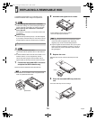
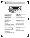
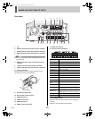
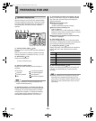
Rear panel
1. Fan
2. RS-232C terminal (when option board is installed)
3. RS-485 terminal A (when option board is installed)
4. RS-485 terminal B (when option board is installed)
z Do not connect the RS-485 A and RS-485 B connectors
to a phone line.
5. RS-485 termination switch (when option board is
installed)
6. LAN terminal (when option board is installed)
7. LAN link indicator (when option board is installed)
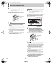
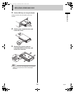
8. Power cord holder
Secure the power cord to the holder using the cord tie
(accessory) as shown in the illustration.
9. AC power socket (AC IN)
10. Wired remote control terminal
11. AUDIO IN terminal
12. AUDIO OUT terminal
13. VIDEO IN terminal
14. VIDEO LOOP OUT terminal
15. VIDEO OUT terminal
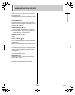
16. Control and alarm terminals
17. ALL RESET switch
Resets the recorder’s microcomputer. Menu settings are
not reset.
Resets the clock and backup mode setting.
ALL
RESET
LAN
OUT
LOOP OUT
VIDEO
NON-REC
COM IN
RESET
OUT OUT OUT OUT OUTOUT FULL FULLCOM COM COMIN IN
CLOCK
WARNING ALARM SERIES
SW
DC IN
REMOTE
IN
OUTIN
OFF ON
RS485
TERMINATE
RS485
RS232C
BA
AUDIO
ALARM
12 63
11 13 1412 15 16
7
10
45
98
17
Power cord tie
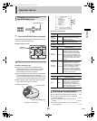
Pin Signal
COM Ground
ALARM IN Alarm input
ALARM RESET IN Alarm reset input
ALARM OUT Alarm output
NON REC OUT Non rec out terminal
COM Ground
CLOCK IN Clock adjust input
CLOCK OUT Clock adjust output
WARNING OUT Warning out terminal
DISK FULL OUT HDD space warning output
ALARM FULL
OUT
Alarm-recording area space warning output
COM Ground
SERIES IN
Input terminal used when recording with
multiple digital video recorders connected.
SERIES OUT
Output terminal used when recording with
multiple digital video recorders connected.
SWITCH OUT Switch output
COM Ground
NON-REC
COM IN
RESET
OUT OUT OUT OUT OUTOUT FULL FULLCOM COM COMIN IN
CLOCK
WARNING ALARM SERIES
SW
ALARM
e05_l8had_us_7.fm Page 15 Friday, March 12, 2004 9:46 AM