


8 Micro Motion 7829 Viscomaster
®
and Viscomaster Dynamic
™
Viscosity Meters
Installation
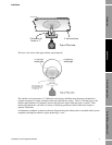
From this, it would appear that almost every installation requires a separate in situ calibration – a very
undesirable situation. The problem is resolved by providing standard calibration geometries which
can be used in all pipe work configurations and thereby allow the factory calibration conditions to be
reproduced in the process.
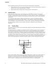
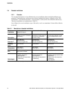
2.2.2 Fluid at the sensor
The fluid in the effective zone of the meter must be of uniform composition and at uniform
temperature. It must be representative of the fluid flow as a whole.
This is achieved either by mixing of the fluid either using a static inline mixer or taking advantage of
any natural pipe condition that tends to cause mixing, such as pump discharge, partially open valves.
The viscometer should be installed downstream where the flow is just returning to laminar flow
conditions.
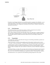
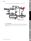
2.2.3 Thermal effects
Avoid temperature gradients in the fluid and in the pipe work and fittings immediately upstream and
downstream of the viscometer.
Always insulate the viscometer and surrounding pipework thoroughly. Insulation must be at least
1" (25 mm) of rockwool, preferably 2" (50 mm) (or equivalent insulating heat jacket) and enclosed in
a sealed protective casing to prevent moisture ingress, air circulation, and crushing of the insulation.
Special insulation jackets are available from Micro Motion for the flow-through chambers, which,
because of the low volumetric flow rates and hence low heat flow, are more vulnerable to temperature
effects.
Avoid direct heating or cooling of the viscometer and associated pipe work upstream and downstream
that is likely to create temperature gradients. If it is necessary to provide protection against cooling
due to loss of flow, electrical trace heating may be applied, provided it is thermostatically controlled
and the thermostat is set to operate below the minimum operating temperature of the system.