


Installation and Configuration Manual 51
Calibration Check
General MaintenanceCalibration Check
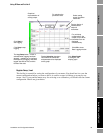
5.3 User calibration checks
5.3.1 Ambient air calibration check
An air check is a simple and convenient method to see if any long term drift or corrosion and
deposition on the tines has occurred.
Ambient air check procedure:
1. Isolate and, if necessary, disconnect the meter from the pipeline.
2. Clean and dry the wetted parts of the meter and leave them open to the ambient air.
3. Apply power to the instrument and check that the time period of the instrument agrees with the
figure shown on the calibration certificate to within ±100 ns. If the meter is not at 20°C,
compensate for this by adding an offset of +110 ns for every °C above 20°C, or by subtracting
an offset of +110 ns/°C below 20°C.
4. Re-fit the meter to the pipeline if serviceable or remove for further servicing.
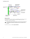
5.3.2 On-line calibration adjustment
An on-line calibration adjustment may be required if:
• The physical boundary surrounding the tines is different from the physical boundary used for
the factory calibration.
• The unit has suffered long term drift or corrosion of the tines.
The meter is a very accurate and stable instrument, and will normally provide good measurements. If
it is suspected of giving incorrect results, you should confirm this by carefully checking the integrity
of the fluid temperature measurement, and compare this with the temperature measurement given by
meter. You should also verify the integrity of the density check measurement. It is only after you
have eliminated all other possible causes of error that you should attempt to make adjustments to the
calibration of meter.
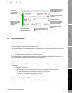
Normally the density calibration adjustment is made by configuring a simple density offset into the
instrument. If a more detailed calibration adjustment is required, such as a two- or three-fluid
calibration adjustment for offset and scale, then refer to Micro Motion.
Calibration adjustment - stable liquids (not for Viscomaster Dynamic):
1. Using ADView (see Using ADView and ProLink II chapter), reset the line density offset
(register 173) to 0, and the line density scaling factor (register 174) to 1.
2. Ensure that the system has reached its stable operating temperature.
3. With the meter operating at typical process conditions, draw off a sample of the liquid into a
suitable container, and note the meter density reading and the operating temperature.
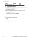
4. Measure the density of the sample under defined laboratory conditions using a hydrometer or
other suitable equipment. Refer this to the operating conditions at the meter.
5. Calculate the density offset required to make the meter measurement the same as the measured
density of the sample.
6. Using ADView’s Register Read/Write tool, configure the meter with the calculated line
density offset (Register 173).
For further details on these procedures, reference should be made to: