


Installation and Configuration Manual 9
Installation
Installation Using ADView and ProLink IIElectrical ConnectionsIntroduction
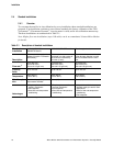
2.2.4 Entrained gas
Gas pockets can disrupt the measurement. A brief disruption in the signal caused by transient gas
pockets can be negated in the signal conditioning software, but more frequent disruptions or serious
gas entrainment must be avoided. This can be achieved by observing the following conditions:
• Keep pipe lines fully flooded at all times
• Vent any gas prior to the viscometer
• Avoid sudden pressure drops or temperature changes which may cause dissolved gases to
break out of the fluid
• Maintain a back pressure on the system sufficient to prevent gas break out (e.g. back pressure
equivalent to twice the ‘head loss’ plus twice the vapour pressure)
• Maintain flow velocity at the sensor within the specified limits.
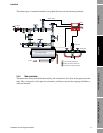
2.2.5 Solids contamination
• Avoid sudden changes of velocity that may cause sedimentation.
• Install the viscometer far enough downstream from any pipework configuration which may
cause centrifuging of solids (e.g. bends).
• Maintain flow velocity at the sensor within the specified limits.
• Use filtration if necessary.
2.2.6 Vibration effects
The 7829 Viscomaster
®
/ Viscomaster Dynamic
™
viscosity meter has been extensively tested under
severe vibration conditions, both in the test laboratory and Marine/Power Station/Burner applications.
The meter is approved according to the Lloyds Register standard, levels ENV 1, 2 and 3 and operates
correctly up to the classification level of ENV4 (vibration test 2). This vibration level, ENV 4
includes correct operation at vibration levels of 4 g rms between frequencies of 5–100 Hz, and is used
to describe the requirements for engine mounted equipment.
If vibration levels exceed these limits, or the meters are not installed as recommended by Micro
Motion, Micro Motion cannot take responsibility for the correct operation of these units.
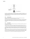
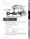
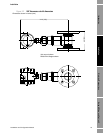
2.3 General fitting notes
The 7829 Viscomaster
®
/ Viscomaster Dynamic
™
viscosity meter uses a 1.5” Swagelok style of fitting
which requires no seals, minimizing maintenance and spares. These fittings are leak proof over a wide
range of pressure and temperature conditions, and during rapid temperature cycling, which may occur
during the transfer from HFO to distillate fuel.
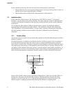
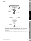
The meter should normally be installed horizontally, with the slot between the tines vertical; this
ensures that, for low flow rates, any solids or gas bubbles are not trapped. When installed in a
flow-through chamber, however, provided that the flow rate is within the recommended range, the
transmitter can be mounted horizontally or vertically.
Allow at least 7.8” (200 mm) clearance to enable the meter to be removed from the fitting.