


Installation and Configuration Manual 29
Electrical Connections
Installation Using ADView and ProLink IIElectrical ConnectionsIntroduction Installation Using ADView and ProLink IIElectrical ConnectionsIntroduction Installation Using ADView and ProLink IIElectrical ConnectionsIntroduction Installation Using ADView and ProLink IIElectrical ConnectionsIntroduction
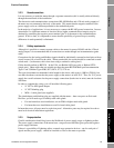
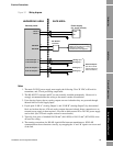
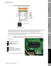
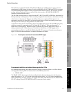
Figure 3-5 4–20 mA output using the main power supply
However, if split-pads “LNK A” (Analog Output 1) and “LNK B” (Analog Output 2) by the terminal
block are ‘broken’, they become isolated and require direct connections to another external
20–28 VDC power supply. A second or third external 20–28 VDC supply can be used.
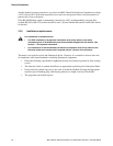
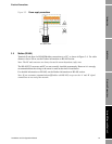
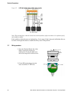
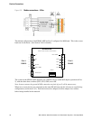
To isolate the analog outputs from internal power, use a sharp knife to cut the fine metal strip (or
trace) for the appropriate split-pad (see Figure 3-6).
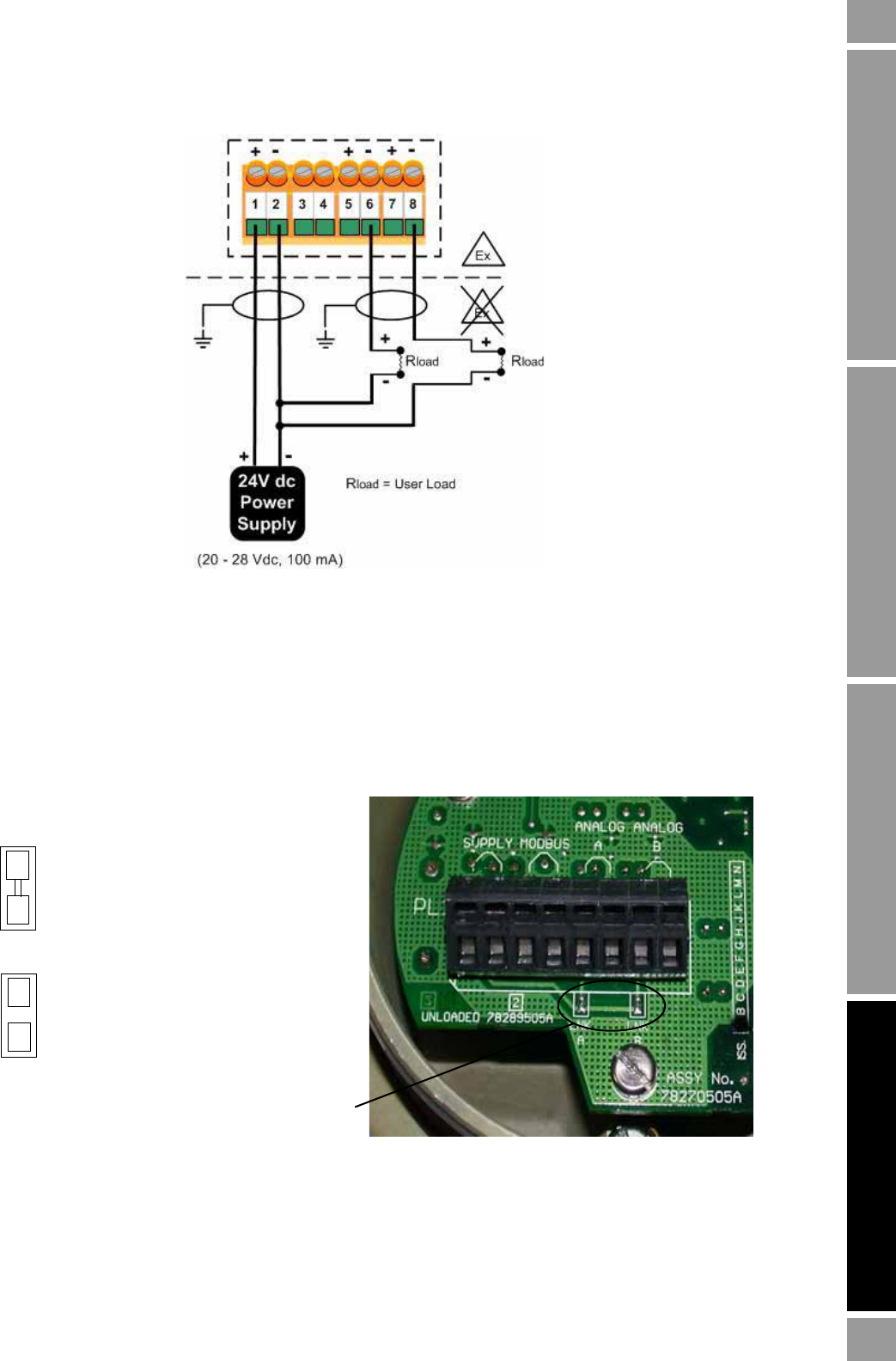
Figure 3-6 Isolating an analog output from internal power (for external power connection)
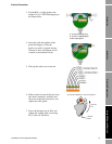
Example split-pads
Non-isolated analog output
(default)
Connected to internal power
(split-pad with trace)
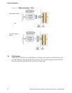
Isolated output
Disconnected from internal power
for external power connection
(split-pad with broken, or cut, trace)
Location of LNK A and LNK B split-pads