


Installation and Configuration Manual 23
Electrical Connections
Installation Using ADView and ProLink IIElectrical ConnectionsIntroduction Installation Using ADView and ProLink IIElectrical ConnectionsIntroduction Installation Using ADView and ProLink IIElectrical ConnectionsIntroduction Installation Using ADView and ProLink IIElectrical ConnectionsIntroduction
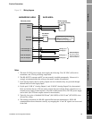
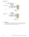
3.2.3 Ground connections
It is not necessary to earth the meter through a separate connection; this is usually achieved directly
through the metalwork of the installation.
The electronics and communications connections (RS-485/Modbus and 4-20 mA analog output) of
the meter are not connected to the body of the meter. This means that the negative terminal of the
power supply can be at a different potential to the earthed bodywork.
In the majority of applications, it is not necessary to connect the RS-485 ground connection. In areas
where there is a significant amount of electrical noise, higher communications integrity may be
obtained by connecting the negative power terminal (pin 2) of the meter to the communications
ground. If this is done, it is important to ensure that the possibility of ground loops (caused by
differences in earth potential) is eliminated.
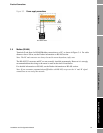
3.2.4 Cabling requirements
Although it is possible to connect separate cables to the meter for power, RS-485 and the 4-20 mA
analog output, it is recommended that all connections are made through one instrumentation-grade
cable.
Connections for the Analog and Modbus signals should be individually screened twisted-pairs with an
overall screen, foil or braid for the cable. Where permissible, the screen should be connected to earth
at both ends. (At the meter, this is best done using a conductive cable gland.)
Cables should conform to BS2538. In the USA, use Belden 9402 (two-pair) or Beldon 85220
(single-pair). Other cables that are suitable are those that meet BS5308 Multi-pair Instrumentation
Types 1 and 2, Belden Types 9500, 9873, 9874, 9773, 9774 etc.
The typical maximum recommended cable length for the above cable types is 1000 m (3200 ft), but
care must be taken to ensure that the power supply at the meter is at least 20 V. Thus, for 24 V power
supply, the overall resistance for the power supply connections (both wires in series) must be less than
100 ohms.
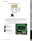
In order to complete the wiring, you will need the following parts:
• ½” NPT to M20 gland adapter
• ½” NPT blanking plug
• M20 x 1 cable gland (not supplied).
The gland adapter and blanking plug are supplied with the meter – these two parts are Exd rated.
However, you will need to get a suitably rated cable gland:
• For non-hazardous area installations, use an IP68 or higher rated cable gland.
• For hazardous area installations use an Exd-rated cable gland.
In hazardous areas, all parts must be explosion-proof. Alternative parts may be required in order to
meet local electrical installation regulations.
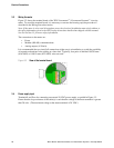
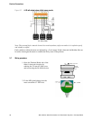
3.2.5 Surge protection
Careful consideration should be given to the likelihood of power supply surges or lightning strikes.
The power supply connections of the meter have a surge arrestor fitted that gives protection against
power supply transients.
If there is a possibility of lightning strikes, external surge protection devices - one for each pair of
signals and the power supply - should be installed as close to the meter as possible.