


22 Micro Motion 7829 Viscomaster
®
and Viscomaster Dynamic
™
Viscosity Meters
Electrical Connections
It is recommended that both outputs are installed, requiring a minimum of eight wires (two for each
output, and two for power). Although you may not immediately require the Modbus connection, it
may be required for in-situ calibration adjustment and future system enhancements, and the cost of
the additional wires is trivial compared to the expense of installing them retrospectively.
A number of factors must be taken into account when planning the electrical installation. These
include:
•Power supply
•EMC
• Ground connections
•Cables
• Surge protection
• Installation in explosive area
• Modbus connections
• Analog connections.
3.2 Installation considerations
3.2.1 Power supply
The power supply to the 7829 Viscomaster
®
/ Viscomaster Dynamic
™
viscosity meter must have the
following requirements:
• Voltage: Nominally 24 VDC, but in the range 20 to 28 VDC.
• Current: for transmitter – 50 mA; for mA outputs – 22 mA per output.
If several meters are to be used within a local area, one power supply can be used to power them all;
where the meters are distributed over a wide area and cabling costs are high, it may be more cost
effective to use several smaller, local power supplies.
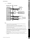
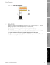
Upon leaving the factory, the two 4-20 mA analog outputs are non-isolated as they are powered
through internal links to the power supply input. However, if split-pads “LNK A” (Analog Output 1)
and “LNK B” (Analog Output 2) by the terminal block are ‘broken’, they become isolated and require
a separate 20-28 VDC power supply (see the 4–20 mA outputs section for details).
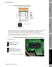
If an RS-232 to RS-485 converter is used (for example to connect to a serial port on a PC), this may
also require a power supply (see the Further information on RS-485 section for details).
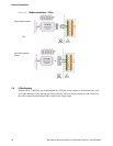
3.2.2 EMC
To meet the EC Directive for EMC (Electromagnetic Compatibility), it is recommended that the meter
be connected using a suitable instrumentation cable containing an overall screen. This should be
earthed at both ends of the cable. At the meter, the screen can be earthed to the meter body (and
therefore to the pipework), using a conductive cable gland.
Care should be taken where there is the possibility of significant common-mode voltages
between different parts of the system. For example, if the meter is locally powered from a power
supply which is at a different potential to the RS-485 ground connection (if used).