48 Micro Motion 7829 Viscomaster
®
and Viscomaster Dynamic
™
Viscosity Meters
Calibration Check
5.1.3 Instrument calibration
Each meter is issued with its own calibration which is programmed into the instrument electronics
before it leaves the factory. Under normal circumstances it should not be necessary to re-calibrate the
meter provided it is used in the environment for which it was calibrated originally.
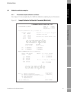
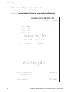
The calibration data is shown on a calibration certificate supplied with the instrument. The calibration
contains the following:
• The instrument serial number
• Four typical points in the output signal Quality Factor / Viscosity relationship, across the
meter’s operating range. This relationship is using the general viscosity equation coefficients,
which are also listed.
• Several sample points from the output signal/density relationship. These have been calculated
using the general density equation with the calibrated coefficients listed.
• Temperature coefficient data, K18 and K19; this defines the correction which should be
applied to achieve the best density accuracy if the instrument is operating at product
temperatures other than 20 °C.
• One instrument air (density) data point for check calibration purposes.
The values for all the V and K coefficients shown on the calibration certificate are programmed into
the meter’s registers, and should not be altered.
Note: If the meter is used in an application dissimilar to the one for which it was originally
calibrated, it may be necessary to re-calculate the V and K coefficients. Contact Micro Motion for
further details.
5.1.4 General viscosity equation
The General Viscosity Equation, used to calibrate the meter and shown in the Calibration certificate
is:
η = V0 + V1 / Q
2
+ V2 / Q
4
where η is the calculated viscosity, Q is the quality factor of the tuning fork, and V0, V1 and V2 are
viscosity coefficients, derived from the factory calibration data and selected to optimise the accuracy
of the viscosity measurement across the calibrated viscosity range for the known physical conditions.
5.1.5 General density equation
The General Density Equation, used to calibrate the meter and shown in the Calibration certificate is:
ρ = K0 + K1τ + K2τ
2
where ρ is the calculated density, τ is the time period (in μs) of the tuning fork, and K0, K1 and K2
are density coefficients, derived from the factory calibration data and selected to optimise the
accuracy of the density measurement across the calibrated density range.
Temperature effects are also compensated for using a second equation:
ρ’ = ρ( 1 + K18(t - 20)) + K19(t - 20)
where ρ’ is the new (temperature compensated) density value, t is the measurement temperature, and
K18 and K19 are temperature correction coefficients.


