


Installation and Configuration Manual 27
Electrical Connections
Installation Using ADView and ProLink IIElectrical ConnectionsIntroduction Installation Using ADView and ProLink IIElectrical ConnectionsIntroduction Installation Using ADView and ProLink IIElectrical ConnectionsIntroduction Installation Using ADView and ProLink IIElectrical ConnectionsIntroduction
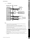
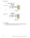
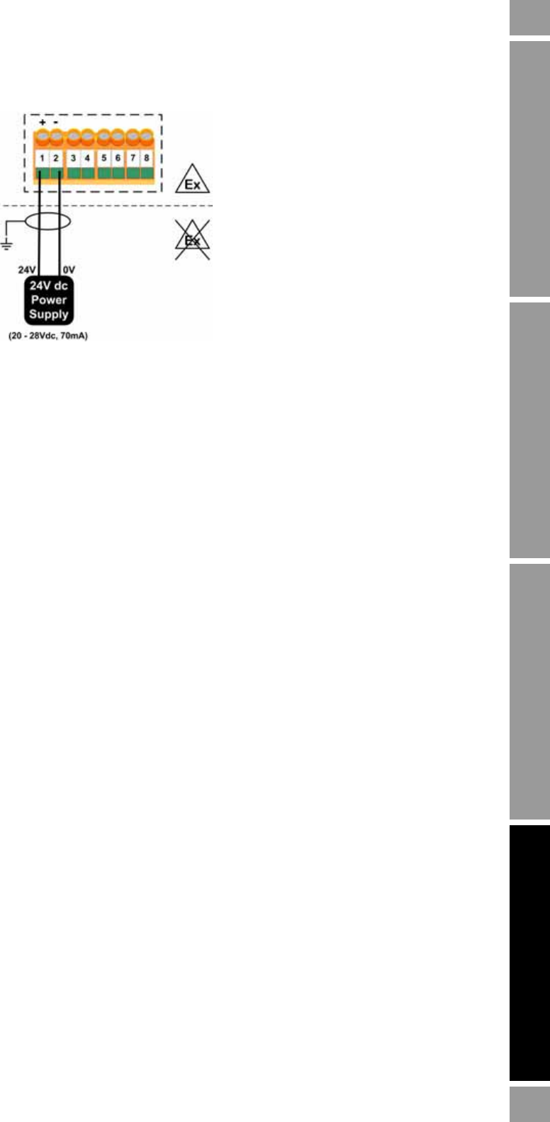
Figure 3-3 Power supply connections
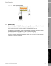
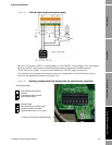
3.5 Modbus (RS-485)
Terminals 3 and 4 are for RS-485/Modbus connections to a PC, as shown in Figure 3-4. For cable
distances above 100 m, see the Further information on RS-485 section.
Note: The PC and converter are always located in a non-hazardous (safe) area.
The RS-485/232 converter and PC are not normally installed permanently. However it is strongly
recommended that the wiring to the meter is made at the time of installation.
For detailed information on RS-485, see the Further information on RS-485 section.
Note: If you encounter communication difficulties with RS-485, swap over the ‘A’ and ‘B’ signal
connections at one end of the network.