


32 Micro Motion 7829 Viscomaster
®
and Viscomaster Dynamic
™
Viscosity Meters
Electrical Connections
3.8 Further information on RS-485
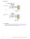
3.8.1 RS-485
The meter’s Modbus communications uses the RS-485 electrical standard. This uses the difference
between the two signal cores to transmit and detect logic levels, and is therefore able to tolerate
significantly higher levels of common mode noise than RS-232, which uses the voltage between the
signal core and a common earth. A brief summary of some typical characteristics of the two
standards is given below.
A converter is required for communication between the two standards. Further details are given in
Section 3.8.2.
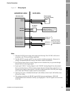
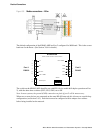
Only two signal connections are required for RS-485, usually called A and B, sometimes ‘+’ and ‘–‘.
Note: Unfortunately, different manufacturers have interpreted the standard in different ways. Some
have a ‘logic 1’ represented by signal A being more positive than signal B, others have made the
opposite interpretation. If you encounter communication difficulties with RS-485, the first remedy is
to swap over the ‘A’ and ‘B’ signal connections at one end of the network.
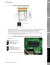
For areas which may experience high common mode signals, a third conductor can be used as a
ground reference for the communications signals. If used, this should be connected to Terminal 2
(Power supply negative) on the meter.
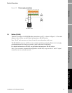
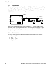
3.8.2 RS-485 to RS-232
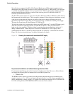
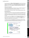
Converters are available from a number of sources, and can range from simple in-line devices that
simply plug into a PC’s RS-232 port, to programmable devices with full isolation between the two
networks.
Note: The meter uses a half-duplex implementation of RS-485, such that the A and B signals are used
for data transmission in both directions. This requires that the RTS line is toggled to indicate the
transmission direction. This can be done by the host computer, or automatically by an RS-485/232
converter which has the facility to do so. If you are using Windows NT, 2000 or XP on your PC, you
should use a converter which automatically changes RTS (as detailed below) otherwise the link may
not work correctly.
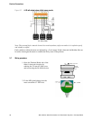
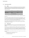
For simple installations, where the following conditions are valid, a simple in-line converter will be
satisfactory:
• The Modbus network is less than about 150 ft (50 m).
• The number of devices on the bus is low.
• No common mode problems.
RS-485 RS-232
Signal detection Differential Single-ended
Receiver threshold 200 mV +1.5 V
Meter output swing 0 to +5 V (no load)
+2 to +3 V (120 ohm load)
± 8 V