


35 Micro Motion 7829 Viscomaster
®
and Viscomaster Dynamic
™
Viscosity Meters
Electrical Connections
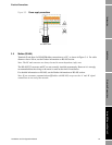
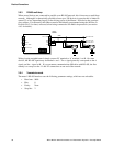
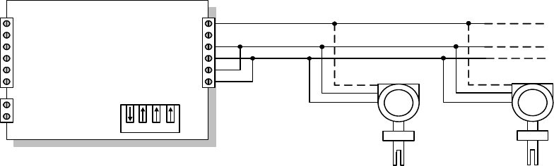
3.8.3 RS-485 multi-drop
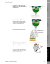
When several devices are connected in parallel on an RS-485 network, this is known as a multi-drop
network. Although it is theoretically possible to have up to 256 devices, in practice this is limited to
around 32 or less, depending largely on the driving power of the Master. Each device has a unique
slave address. For the meter, this address must be individually programmed using the ADView or
ProLink II (v2.9 or later) software, before being connected to the multi-drop network (see section
4.4.3 for details).
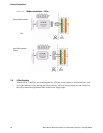
Wiring is quite straightforward: simply connect ‘B’ terminal to ‘A’ terminal, A to B. On some
devices, the RS-485 signals may be marked + and –. The + signal generally corresponds to the A
signal, and the – signal to B. If you encounter communication difficulties with RS-485, the first
remedy is to swap over the ‘A’ and ‘B’ connections at one end of the network.
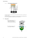
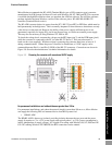
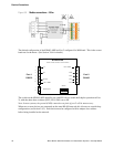
3.8.4 Transmission mode
The meter’s RS-485 interface uses the following parameter settings, which are not selectable:
• Baud rate: 9600
• Bits: 8
• Parity: None
• Stop bits: 2
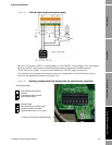
KD485-ADE
Tx
Rx
RTS In
Port 1 GND
Power Input
1
2
3
4
5
6
7
8
-
+
6
5
4
3
2
1
Port 2
RS485
RxB
Port 2 GND
RxA
TxA
TxB
A
B
A
B
GND
GND
3
4
2
A
B
GND
3
4
2