


26 Micro Motion 7829 Viscomaster
®
and Viscomaster Dynamic
™
Viscosity Meters
Electrical Connections
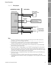
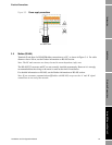
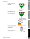
3.3 Wiring the meter
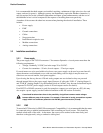
Figure 3-2 shows the terminal board of the 7829 Viscomaster
®
/ Viscomaster Dynamic
™
viscosity
meter. To reveal the terminal board, it is necessary to unscrew the housing cap; the procedure is
described in the Wiring Procedure section.
Note: If the meter is to be used in hazardous areas, the electrical installation must strictly adhere to
the safety information given in the ATEX safety instructions booklet that shipped with this manual.
See also Section 1.1 for more safety information.
The connections to the meter are:
•Power
• Modbus (RS-485) communications
• Analog outputs (4-20 mA).
It is recommended that you install all connections (eight cores) at installation, to avoid the possibility
of expensive alterations to the cabling at a later date. Typically, four pairs of shielded 19/0.30 mm
2
(#16 AWG) to 19/0.15 mm
2
(#22 AWG) wires are used.
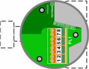
Figure 3-2 View of the terminal board
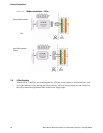
3.4 Power supply input
Terminals 1 and 2 are for connecting an external 24 VDC power supply, as guided in Figure 3-3.
Ensure that the loop resistance of the cable(s) is such that the voltage at the meter terminals is greater
than 20 volts. (The maximum voltage at the meter terminals is 28 VDC.)