


Installation and Configuration Manual 25
Electrical Connections
Installation Using ADView and ProLink IIElectrical ConnectionsIntroduction Installation Using ADView and ProLink IIElectrical ConnectionsIntroduction Installation Using ADView and ProLink IIElectrical ConnectionsIntroduction Installation Using ADView and ProLink IIElectrical ConnectionsIntroduction
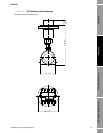
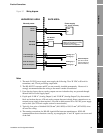
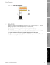
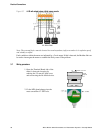
Figure 3-1 Wiring diagram
Notes
1. The main 24 VDC power supply must supply the following: 20 to 28 VDC at 50 mA for
transmitter; and, 22 mA per analog output used.
2. The RS-485/232 converter and PC are not normally installed permanently. However it is
strongly recommended that the wiring to the meter is made at installation.
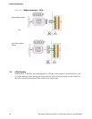
3. Upon leaving factory, the two analog outputs are non-isolated as they are powered through
internal links to Power Supply Input.
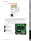
4. If split-pads “LNK A” (Analog Output 1) and “LNK B” (Analog Output 2) by the terminal
block are broken, the two 4-20 mA analog outputs become isolated; direct connections to an
external power supply is then required. A second or third external 20 to 28 VDC power supply
can be used. (See 4-20 mA outputs section for more details).
5. Typically, four pairs of shielded 19/0.30 mm
2
(#16 AWG) to 19/0.15 mm
2
(#22 AWG) wires
are used for wiring.
6. The naming conventions for RS-485 signals differ between manufacturers. If RS-485
communications do not function correctly, try swapping the ‘A’ and ‘B’ signals over at one end
of the link.
HAZARDOUS AREA SAFE AREA
Viscosity meter
Power +
Power -
RS-485 A
RS-485 B
4-20 mA output 1 +
4-20 mA output 1 -
Power supply
(
20...28 Vdc at 50 mA)
+ 24V
0V
RS-485/232
converter
To RS-232 port on a PC running
ADView or ProLink II (v2.9 or later)
software for monitoring,
maintenance and configuration.
Analog o/p +
Analog o/p -
1
2
4
3
5
6
4-20 mA output 2 +
4-20 mA output 2 -
Analog o/p -
7
8
Analog o/p +
Passive outputs
(see the 4-20 mA
outputs section for
more information)