10 Micro Motion 7829 Viscomaster
®
and Viscomaster Dynamic
™
Viscosity Meters
Installation
2.4 Standard installations
2.4.1 Overview
To overcome the need for in situ calibration for every installation, three standard installations are
proposed. If an installation conforms to one of these standards, the factory calibration of the 7829
Viscomaster
®
/ Viscomaster Dynamic
™
viscosity meter is valid, and in-situ calibration unnecessary.
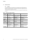
The three installations are summarized in Table 2-1.
Note: Higher flow rate installations (up to 100 m
3
/hr) can be accommodated. Contact Micro Motion
for details.
Table 2-1. Descriptions of standard installations
Standard
installation
VAF VISCOTHERM /
NAKAKITA Retrofit
VAF VISCOSENSE Retrofit Flow-through chamber
Description
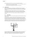
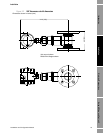
Viscomaster tines project into
adapter kit with 2½“ Schedule
40 boundary.
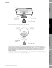
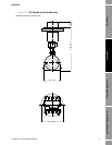
Viscomaster tines are
contained in a side pocket off
the main flow, recessed by
25.4 mm (1 inch).
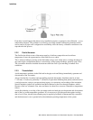
Viscomaster tines are contained in
a flow-through chamber in which
fluid is circulated from the main
flow.
Flow rate
(1)
(1) Viscomaster tines project into adapter kit with 2-½“ Schedule 40 boundary and retracted by 1” (25 mm).
10 to 330 l/min
(0.6 to 20 m
3
/hr)
(2.6 to 87 US gal./min).
10 to 330 l/min
(0.6 to 20 m
3
/hr)
(2.6 to 87 US gal./min).
10 to 330 l/min
(0.6 to 20 m
3
/hr)
(2.6 to 87 US gal./min).
Viscosity
limits
Up to 100 cSt. Up to 100 cSt Up to 100 cSt.
Temperature
-50 to 200°C
(-58 to 392°F).
-50 to 200°C
(-58 to 392°F).
-50 to 200°C
(-58 to 392°F).
Main flow pipe
size
As defined by capillary
Viscomaster chamber.
50 mm (2"). 50 mm (2").
Advantages
• Simple replacement of
capillary viscometer.
• Fast response.
• Good flow and temperature
conditioning.
• Simple replacement of
torsional viscometer.
• Fast response.
• Good flow and temperature
conditioning.
• Adaptable installation to any
diameter main pipe and for tank
applications.
• Ideal for flow and temperature
conditioning.
• Fast response.


