


18 Micro Motion 7829 Viscomaster
®
and Viscomaster Dynamic
™
Viscosity Meters
Installation
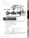
2.5 Commissioning
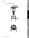
1. Once the pipework installation has been prepared, and before installing the 7829 Viscomaster
®
/ Viscomaster Dynamic
™
viscosity meter and thermal insulation, fit a blanking compression
nut to the meter mounting, and pressurise and flush the system.
2. Isolate the system, depressurize and remove the blanking compression nut.
3. Install the meter, and tighten the fitting nut, but do not fit the thermal insulation.
4. Slowly pressurize the system and check for leaks, particularly if the normal operating
temperature is high, or the meter has been fitted cold; tighten as necessary.
5. Now tighten the nut again, if necessary. Once you are satisfied with the integrity of the seal,
the insulation can be fitted.
6. Once the system has stabilized and is leak free, fit the insulation material.
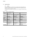
2.6 During normal running
Observe and record the normal operating temperatures and viscosity readings. You can monitor the
system using ADView or ProLink II. (See the Using ADView and ProLink II chapter.)
When several systems are run in parallel and use the same fuel source, comparison of the readings
between installations can be a useful indicator of possible system faults. Differences between readings
or changes from the normally observed conditions should always be investigated to confirm that
instrumentation is functioning correctly.
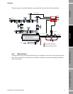
Particular attention should be paid to the conditions before and after engine shutdowns in order to
detect any possibility of asphaltenes coating (precipitation of asphaltenes from the HFO caused by
dilution with distillate fuel) which may cause the instrument to read high. If the re-circulation flow is
high enough or the instruments have been supplied with PFA coating, asphaltenes or any other
deposits should quickly be removed and the expected operating temperatures should be restored.
If the meter is still reading high and the oil quality is known not to have changed, then the instrument
should be removed and cleaned with a rag. Removal should only be performed in accordance with the
engine or burner manufacturers’ recommendations or in accordance with safe site practice. This must
include isolation and depressurization.
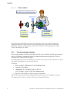
2.7 Removal and refitting procedure
Check that the isolation valves have been fully closed, remove insulation and allow to cool to a safe
level (cooling will tend to reduce any retained pressure) and de-pressurize the system if a drain valve
or pressure relieving valve is fitted.
All national and international safety regulations should be observed.
Observe safe working practice, wear protective clothing and safety glasses, and use suitable
gloves to prevent burns or absorption of hot oil.