


Installation and Configuration Manual 31
Electrical Connections
Installation Using ADView and ProLink IIElectrical ConnectionsIntroduction Installation Using ADView and ProLink IIElectrical ConnectionsIntroduction Installation Using ADView and ProLink IIElectrical ConnectionsIntroduction Installation Using ADView and ProLink IIElectrical ConnectionsIntroduction
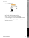
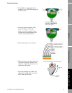
3. Fit the M20 x 1 cable gland to the
adapter. Fit a ½” NPT blanking plug to
the unused hole.
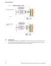
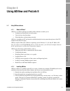
4. Insert the cable through the cable
gland and adaptor so that the
multi-core cable is gripped leaving
200 mm of free, unscreened wire to
connect to the terminal blocks.
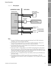
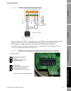
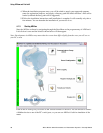
5. Wire up the cable cores as shown
6. When you have screwed the wires into
the correct terminals, carefully tuck
the wires around the electronics, and
tighten the cable gland.
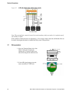
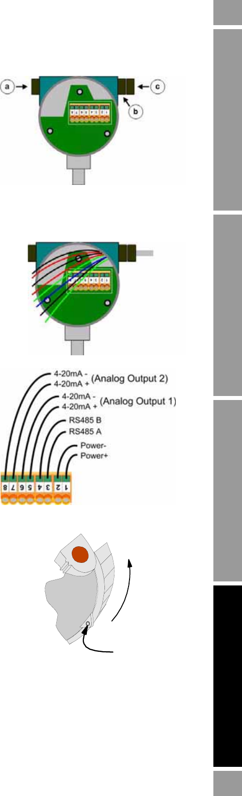
7. Screw the housing cap on fully and
tighten the locking grub screw using
the 2.5 mm AF hex drive.
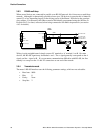
a: ¾” NPT Blanking Plug.
b: ¾” NPT to M20 adaptor.
c: M20 cable gland.
TIGHTEN
CAP
TIGHTEN
GRUB
VIEW FROM UNDERNEATH THE ELECTRONICS
: