


12 Micro Motion 7829 Viscomaster
®
and Viscomaster Dynamic
™
Viscosity Meters
Installation
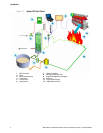
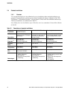
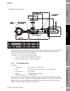
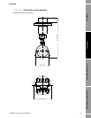
Figure 2-1 Meter orientation
Note: All drawings and dimensions given in the following sections are derived from detailed
dimensional drawings. They are given here for planning purposes only. Before commencing
fabrication, reference should always be made to the current issue of the appropriate drawings -
contact Micro Motion for details.
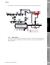
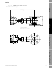
2.4.3 Flow-through chamber installation
Flow-through chambers are fabricated by Micro Motion, and are available with either weld prepared
ends or with flange or compression fittings for connection into the process pipe lines. They are
available with 2" NB inlet and outlet pipes.
Note: The length of the inlet and outlet pipes must not be altered, otherwise the temperature response
and stability of the fitting may be adversely affected.
Conditions:
• Flow: constant, 5–300 l/min for 3" sch 80 calibration bore.
• Viscosity: 0.5 to 100 cP
• Temperature: -50 °C to 200 °C (–58 °F to 392 °F)
[-40 °C to 200 °C (-40 °F to 392 °F) in hazardous areas]
• Pressure: 70 bar @ 204 °C, subject to process connections.
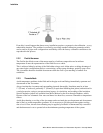
The PT100 is a direct insertion type, without a thermowell, and uses a ¾" Swagelok connection.
The diagram below shows an example of this type of standard installation.
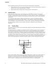
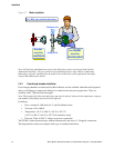
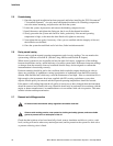
Bubbles rise!
Solids sink!
the slot
must be
ver tical
.
For ALL pipe and flow directions
.
the meter
must be
horizontal