


30 Micro Motion 7829 Viscomaster
®
and Viscomaster Dynamic
™
Viscosity Meters
Electrical Connections
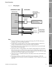
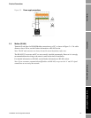
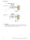
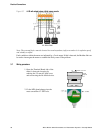
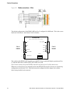
Figure 3-7 4–20 mA output using a third power supply
Note: The external device must be located in a non-hazardous (safe) area unless it is explosion proof
and suitably certified.
Fault conditions within the meter are indicated by a 2 mA output. If this is detected, the Modbus link can
be used to interrogate the meter to establish the likely cause of the problem.
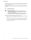
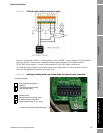
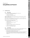
3.7 Wiring procedure
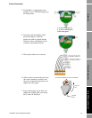
1. Open the Terminal Board side of the
meter’s electronics housing by
undoing the 2.5 mm AF grub screw
and unscrewing the lid anticlockwise.
2. Fit the M20 gland adaptor into the
most convenient ½” NPT hole.
GRUB
SCREW
UNDO THIS CAP