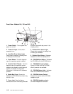
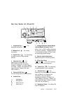
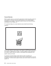
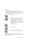
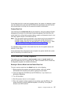
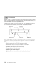
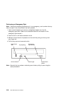
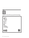
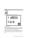
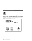
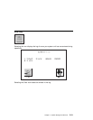
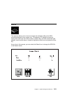
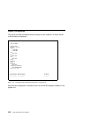
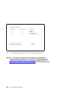
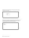
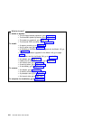
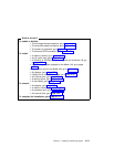
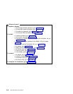
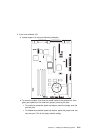
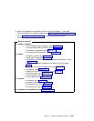
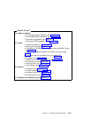
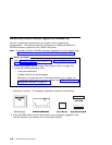
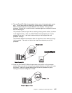
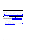
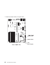
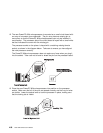
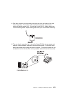
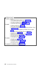
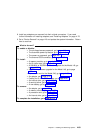
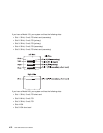
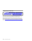
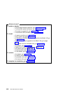
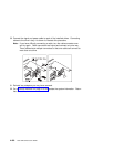
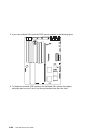
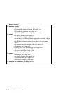
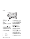
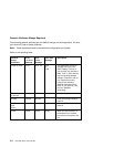
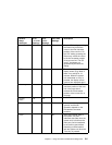
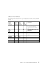
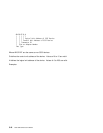
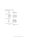
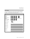
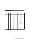
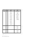
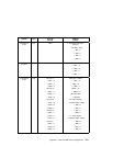
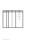
Processor-PCI bus
- PCI bus
Memory module in system planar
---1
Memory module in card
-A--1
Integrated PCI adapters for
4-A ISA bus (Integrated PCI-ISA bridge)
4-B Secondary PCI bus (Integrated PCI-PCI bridge)
4-C Integrated PCI SCSI controller
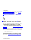
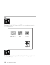
Non-integrated PCI adapters
4-1 Any PCI card in slot 1
4-2 Any PCI card in slot 2
Integrated ISA adapters
1-A Diskette adapter
1-B Parallel port adapter
1-C Serial port 1 adapter
1-D Serial port 2 adapter
1-E Keyboard adapter
1-F Mouse adapter
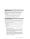
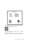
Non-integrated ISA adapters
1-1 First ISA card defined/configured
1-2 Second ISA card defined/configured
Device attached to SCSI controller
4-C-1-4, Device attached to Integrated PCI SCSI controller
Chapter 5. Using the Online and Standalone Diagnostics 5-17