


MAP 1520: Power
Notes:
1. This is not a start of call MAP. Use this Power MAP only if you have been
directed here from a MAP step in the Diagnostics Information for Multiple Bus
Systems.
2. The Model 150 has a power LED located on the operator panel. When the
system is powered on the LED should be on solid.
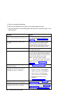
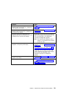
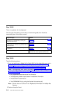
This procedure is used to locate power problems in system units. If a problem is
detected, this procedure helps you isolate the problem to a failing unit.
Observe the following safety notice during service procedures.
DANGER
An electrical outlet that is not correctly wired could place hazardous
voltage on metal parts of the system or the devices that attach to the
system. It is the responsibility of the customer to ensure that the outlet
is correctly wired and grounded to prevent and electrical shock.
Before installing or removing signal cables, ensure that the power
cables for the system unit and all attached devices are unplugged.
When adding or removing any additional devices to or from the system,
ensure that the power cables for those devices are unplugged before
the signal cables are connected. You must disconnect all power cables
from the existing system before you add a device.
Use one hand, when possible, to connect or disconnect signal cables
to prevent a possible shock from touching two surfaces with different
electrical potentials.
During an electrical storm, do not connect cables for display stations,
printers, telephones, or station protectors for communication lines.
CAUTION:
This product is equipped with a three–wire power cable and plug for the user's
safety. Use this power cable with a properly grounded electrical outlet to avoid
electrical shock.
Chapter 2. Maintenance Analysis Procedures (MAPs) 2-15