


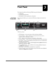

Installing the TDR6
01-0870-401B 01/03 11
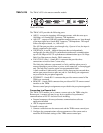
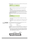
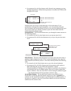
To cable the Analog Audio terminal block connectors:
1. Press the detent using a screw driver with a maximum width of .15 inch to
open the clamp below it.
2. Insert audio cable wire into the clamp.
3. Release the detent. The clamp will close tightly on the inserted wire.
Opening the clamp requires firm pressure. The required pressure may temporarily deflect the rear
panel, but will not damage the unit.
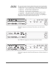
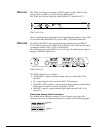
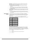
TAUD-6100 The TAUD-6100 four-channel audio module process four MPEG-2 audio streams
and provides AC3 audio passthrough.
TAUD-6100 Ports
These four audio ports output unbalanced digital AES/EBU audio on female BNC
75 Ω connectors.
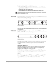
TDEM-6110 The TDEM-6110 QPSK demodulator module enables the TDR6 to perform as an
SDTV or HDTV IRD with four L-band inputs.
TDEM-6110 Ports
The LNB 1 through LNB 4 connectors are F-Type, 75 Ω female connectors that
accept RF from 950 to 2150 MHz, at power levels between -65 dBm and
-25 dBm.
Cabling the TDEM-6110
LNB ports A through D are used to connect the TDR6 to up to four satellite
antenna LNBs. Although each of the four RF inputs can be independently
configured, only one port may be active at a time.
The IFL cable loss should not exceed 25 dBm to ensure reliable IRD operation
over a broad range of satellite operating parameters and varying weather
conditions.
LNB Power
In the default configuration, the TDR6 does not supply DC power to the LNB.
However, the TDEM6110 can be configured so that the active LNB IN port
outputs LNB DC power at <500 mA DC at either 13V or 18V.
NOTE
AUDIO A AUDIO B
AUDIO C AUDIO D
PUSH
HERE
AES/EBU TAUD-6100
LNB B
LNB DLNB C
LNB A
TDEM-6110