


58 01-0870-401B 01/03
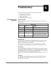
Troubleshooting
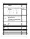
Receive Carrier Offset
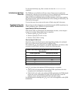
The Offset value displays the difference, in MHz, between the actual receive
carrier frequency and the frequency determined by subtracting the LO Freq
parameter from the RF Freq parameter ( ), which have been entered by the
user. To achieve carrier lock, the difference between the two frequencies, as
shown in the Offset, must be less than 2MHz; however, to achieve optimum
performance, the carrier Offset should be as close to zero as possible.
While the TDR6 is trying to lock onto a receive carrier, the Offset value is not
valid. When the TDR6 is locked onto the receive carrier, the Offset displays the
number of MHz you need to adjust the RF Freq in order to achieve optimum
performance.
To achieve optimum performance, the Offset frequency should be as close to 0 as
possible.
For the procedures used to query the offset parameter and to adjust the RF and LO
parameters, refer to the chapter on configuration.
Demodulator Does Not Lock
If the demodulator does not lock, verify that the receive signal E
b
/N
0
and power
levels are above the minimum DVB limits. If the receive signal E
b
/N
0
and power
levels are sufficient, confirm that following settings match those of the modulator:
■ RF frequency (RF Freq)
■ LO frequency (LO Freq)
■ Transport stream data rate (Data Rate)
■ Viterbi code rate (Code Rate)
Demodulator Locks Intermittently
If the demodulator locks intermittently, but the decoder does not lock, confirm
that the E
b
/N
0
level is above the minimum DVB limits. If the E
b
/N
0
is sufficient,
confirm that the Viterbi code rate is set correctly.
Performance Problems
If performance is low, take the following actions:
■ Replace the cable from the LNB to the input port on the TDR6.
■ Check for ground loop potential.
■ Check the carrier offset parameter. If carrier is off by more than 1.5 Mhz from
the center, then change RF or LO parameters to reduce the carrier offset.
For the procedures used to query the offset parameter and to adjust the RF and
LO parameters, refer to the chapter on configuration.
■ Check adjacent channel spectrum to ensure that there is no adjacent channel
interference
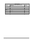
■ Ensure that the bit rate does not exceed the maximum bit rate for a given
transponder bandwidth.
Refer to the QPSK demodulator appendix for a table providing information
related to bit rates versus transponder bandwidth.
RF LOÐ