


50 01-0870-401B 01/03
Configuring the TDR6
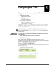
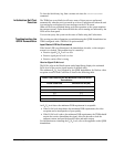
Configuring the L-Band Carrier Frequency
The LNB downconverter outputs a DVB-compliant, modulated L-band carrier at
an IF frequency which is input to the demodulator. For proper operation, the input
L-Band carrier frequency must be equal to where:
■ RF is the carrier frequency at the input to the LNB
■ LO is the local oscillator frequency within the LNB
Note that it is not the absolute values of RF and LO that are important, just the
difference.
You must configure both the RF and LO parameters. If the entered RF or LO
parameters are incorrect, the actual carrier frequency will be different from the
programed carrier frequency.
To determine the difference, if any, query the Offset parameter.
While the TDR6 is acquiring carrier lock, the Offset parameter is not valid. Once
lock has been achieved, the offset parameter provides a valid measure of the
difference between the actual receiver carrier and the calculated receiver carrier.
To achieve carrier lock, the Offset must be less than 2 MHz. For optimum
performance, the Offset parameter should be as close to zero as possible.
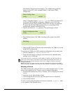
To configure the L-band carrier frequency:
1. Check the Offset parameter.
2. Adjust the RF and LO parameters if necessary.
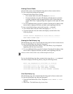
To query the offset using the front panel:
Select Details>Input>Status>Offset.
To adjust the RF and LO parameters using the front panel:
1. When the decoder is locked onto the receive carrier, query the offset
parameter using the front panel Details>Input>Status>Offset menus or the
remote command
DMD.x OFFSET.
The Offset parameter must be less than 2 MHz to achieve carrier lock. For
optimum performance, it should be zero.
2. Verify that you have entered the correct LO value. Refer to the LNB
documentation.
3. Adjust the RF parameter, if necessary.
a. Subtract the Offset parameter from the current RF parameter ( ).
b. Enter the result as the new RF parameter using the front panel
Details>Input>Config>Demod>RF_x>RF Freq menu or the remote
command
DMD.
x
RF <new value>.
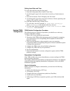
Example: Configuring the Demodulator
This is an example of configuring a TDR6 with a TDEM-6110 option module
installed. Use this example as a guide, substituting your site-specific parameters.
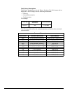
Step 1: In this example, assume that your operations require the following
parameters:
■ Input: RF
■ Modulation: QPSK
■ RF Freq: 11.774 GHz
■ LO Freq: 10.750 GHz
■ Data Rate: 8.448 Mbps
■ Code Rate: 3/4
■ LNB Power: 13V
RF LOÐ
RF LOÐ