


Demodulator Application Notes
01-0870-401B 01/03 81
G
Demodulator
Application Notes
This appendix contains additional technical information for the TDEM-6110
Demodulator option module, including information on:
■ Configuration
■ Rates and channel spacing
■ Estimating E
b
/N
0
■ Troubleshooting
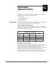
Configuration This section provides technical information to supplement the basic configuration
procedures provided in the chapter on configuring the TDR6.
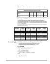
Industry Standard LNB Frequencies
The tuner input frequency for the demodulator is divided into two components
(RF and LO) to correlate with industry standards. The following table lists the RF
range for common LNB LO frequencies.
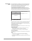
Demodulator Tuner SAW Filter
The demodulator tuner has a SAW filter (bandpass) for rejecting out-of-band
noise. It is important that you correctly specify the input L-Band frequency to
insure that the input spectrum is within the passband of the filter.
Check the Offset parameter to confirm that the acquired carrier is within 2 Mhz of
the location you specified when entering the RF and LO parameters.
For the procedures used to query to offset parameter and to correct the offset by
adjusting the RF and LO parameters, refer to the chapter on configuration.
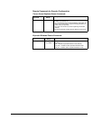
RF Ranges for LO Frequencies
RF Range
(Mhz)
LNB LO (Mhz)
Input L-band
Range (Mhz)
Type
3450 - 4200 5150 950 - 2150 C band
10950 - 11700 10000 950 - 2150 —
11700 - 12450 10750 950 - 2150 Domestic Ku Band
12250 - 13000 11300 950 - 2150 —