


•••••••••••••••••••••••••••••••••••••••••••••••••••••••••••••••••••••••••••••••••••••••••••••••••••••••••••••••••••••••••••••••• Beginning
16
AUDIO IN
1
2
3
4
OUT
IN
AUDIO
CASCADE
AUDIO OUT
100-240V
AC IN~
MAX 350mA
DC 12V OUT
CLOCK ADJ
CLOCK ADJ OUT
REC
REC STOP
EMERGENCY
RESERVED
MODE OUT 1 +
MODE OUT 1 —
MODE OUT 2 +
MODE OUT 2 —
MODE OUT 3 +
MODE OUT 3 —
MODE OUT 4 +
MODE OUT 4 —
CALL OUT +
CALL OUT —
GND
GND
GND
GND
1
ALARM IN
2
3
4
5
6
7
8
9
10
11
12
13
14
15
16
RS485 TERM +
RS485 TERM —
P T Z
RS422
+
RS422
—
RS232
1
ALARM OUT
2
3
4
5
6
7
8
9
10
11
12
13
14
15
16
RS-232C
RS485RS485
INOUT
MAIN
OFF ON
RESET
OPTION SLOT
LAN-A LAN-B
STORAGE COM
SERIAL BUSSERIAL BUS
12345678
910111213141516
OUT
IN
CAMERA
OUT
IN
Y/C
OUTPUT B
CLAMPER
CLAMPER
OUTPUT A
VIDEO VIDEO
VIDEO CASCADE
INOUT
1010010100
13 15 16 1714
12
11
2
1
7
4563
108 9
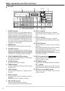
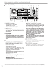
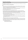
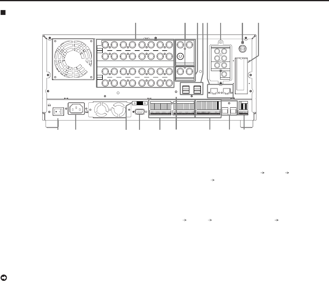
13. ALARM IN terminals
Input terminals for alarm signal.
ALARM OUT terminals
Output terminals for alarm signal.
14. RESET button
Used to reset the unit and turn off the power. At this
time, picture data, menu settings, and the present
time are kept.
15. I/O terminals
CLOCK ADJ terminal
Input terminal to set the present time. Time display
is adjusted to the nearest hour (00 minutes 00 sec-
onds) when this terminal receives the CLOCK ADJ
signal.
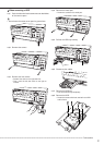
• The on-screen clock is reset to the nearest hour by
applying a signal to the CLOCK ADJ terminal. For
example, if the current time is 11:29:59, it will be
reset to 11:00:00, and if the current time is 11:30:00,
it will be reset to 12:00:00.
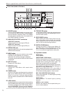
CLOCK ADJ OUT terminal
Output terminal to send the signal to the other
recorders connected for adjusting the clock to the
nearest hour (00 minutes 00 seconds).
REC terminal
Input terminal to start recording. This terminal is not
available during timer recording.
REC STOP terminal
Input terminal to stop recording. This terminal is not
available during timer recording.
EMERGENCY terminal
Input terminal to start EMERGENCY recording im-
mediately.
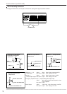
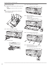
MODE OUT 1 to MODE OUT 4 terminals
Output terminal to indicate the current mode of this
unit. Select the mode of the unit to be output in the
<Mode Out Settings> (Setup Menu System Rear
Terminal Setting Mode Out Settings).
CALL OUT terminals/CALL OUT GND terminal
This is a ISOLATION output terminal. Information
to be transmitted externally consists of CALL OUT
settings made in the <Call Out Settings> (Setup
Menu System Rear Terminal Setting Call Out
Settings) as well as fixed output settings.
DC 12 V OUT terminal
Output the voltage only when both the MAIN switch
and POWER button are turned ON. The maximum
electric current is 350 mA.
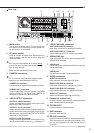
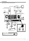
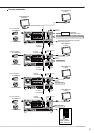
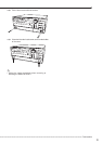
16. RS485 IN/OUT connectors
Connectors for control of cascade recorders. Used
to connect with the other recorders.
17. RS422/RS232C connectors
Connectors for connecting PTZ cameras to oper-
ate pan, tilt, and zoom functions of the camera.
Major operations and their functions (continued)
Rear view (continued)