


80
••••••••••••••••••••••••••••••••••••••••••••••••••••••••••••••••••••••••••••••••••••••••••••••••••••••••••••••••••••••••••••••••••••••••••••••••••••••••••
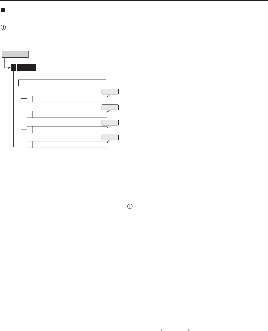
Memory System Menu
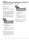
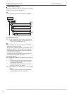
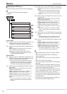
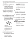
Add/Remove HDD Device
This item is used to set the HDDs for main or copy device.
• You cannot set this item during recording or
playback.
Add/Remove HDD Device
Memory5
1
Internal HDD
1
External HDD (USB HDD)
2
External HDD (SCSI HDD)
3
4
External HDD (NAS HDD)
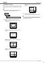
System Menu
steps
1, 2
steps
3, 4
steps
5, 6
steps
7, 8
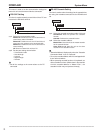
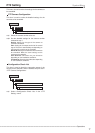
(Internal HDD)
step1. Make sure that the internal HDDs connected are
displayed in the screen of <Internal HDD>.
• Internal A to C indicate the internal device number.
step2. Add or remove the internal HDDs for setting the main
device.
Main: Registers for the main device. The numbers
01 to 03 indicate the recording order.
Free: Does not registered as the main device.
• The button changes between “Main” and “Free”
each time you press the button.
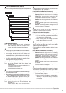
(External HDD)
step3. Make sure that the USB HDDs connected to the
SERIAL BUS port of this unit are displayed in the
screen of <External HDD (USB HDD)>.
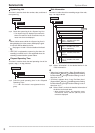
• When the “SB:” button of the desired ID number
is pressed, the access LED on the device
illuminates and you can check the corresponding
HDD which is connected to the SERIAL BUS port.
step4. Add or remove the USB HDD for setting the main or
copy device.
Main: Registers for the main device. The numbers
indicate the recording order.
Copy1: Registers for the copy 1 device. The
numbers indicate the order for writing of data.
Copy2: Registers for the copy 2 device. The
numbers indicate the order for writing of data.
Free: Does not registered as the main or copy
device.
• The button changes in the order of “Main,”
“Copy1,” “Copy2,” and “Free” each time you press
the button.
step5. Make sure that the SCSI HDDs connected are
displayed in the screen of <External HDD (SCSI
HDD)>.
• When the “SCSI:” button of the desired ID number
is pressed, the access LED on the device
illuminates and you can check the corresponding
HDD.
step6. Add or remove the SCSI HDD for setting the main
or copy device.
Main: Registers for the main device. The numbers
indicate the recording order.
Copy1: Registers for the copy 1 device. The
numbers indicate the order for writing of data.
Copy2: Registers for the copy 2 device. The
numbers indicate the order for writing of data.
Free: Does not registered as the main or copy
device.
• The button changes in the order of “Main,”
“Copy1,” “Copy2,” and “Free” each time you press
the button.
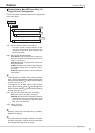
step7. Make sure that the NAS HDDs connected are
displayed in the screen of <External HDD (NAS
HDD)>.
• The NAS number and the IP address set in the
<LAN A (NAS) Setting> are shown on the screen.
step8. Add or remove the NAS HDD for setting the copy
device.
Copy1: Registers for the copy 1 device. The
numbers indicate the order for writing of data.
Copy2: Registers for the copy 2 device. The
numbers indicate the order for writing of data.
Free: Does not registered as the copy device.
• The button changes between “Copy1,” “Copy2,”
and “Free” each time you press the button.
• The available device to be set as the copy 1 device
are:
HDD, DVD-R, DVD-RW, CD-R, CD-RW, USB
memory, and NAS.
The available device to be set as the copy 2 device
are:
HDD, DVD-RW, DVD-R, and NAS.
• Consult your dealer about NAS and SCSI devices
supported.
• The copied data is transmitted in 2 MB units. The copy
of up to 2 MB of the latest data may be delayed. Be
careful when changing the copy device.
• The maximum number of devices connected to serial
bus is 16 including the built-in DVD. This is the total
number of devices for main, copy 1, and copy 2.
• The maximum number of SCSI devices used at the
same time is 6. Attach the optional board to connect
the SCSI devices.
• The order of the main device used for recording is:
internal HDD
USB HDD SCSI HDD.