


18
•••••••••••••••••••••••••••••••••••••••••••••••••••••••••••••••••••••••••••••••••••••••••••••••••••••••••••••••••••••••••••••••••••••••••••••••••••
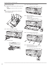
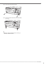
Connections (continued)
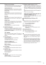
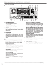
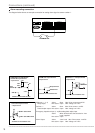
Mode out +/– (1-4) Active: Short Max. Drive current 500 mA DC.
Relay output Non active: Open. Max. Voltage +24 V DC.
Call out +/– Active: Short Max. Drive current 7 mA DC.
Photo coupler output Non active: Open. Max. Voltage +24 V DC.
Emergency input/Alarm input (1-16)/Recording/Clock adjust input
Active: When terminals are short-circuited or “Low”
Level is applied.
Non active: Open.
Alarm Output Active: “Low” Level Max. Drive current 7 mA DC.
Non active: Open. Max. Voltage +24 V DC.
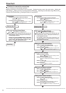
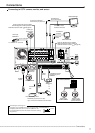
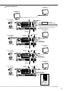
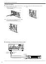
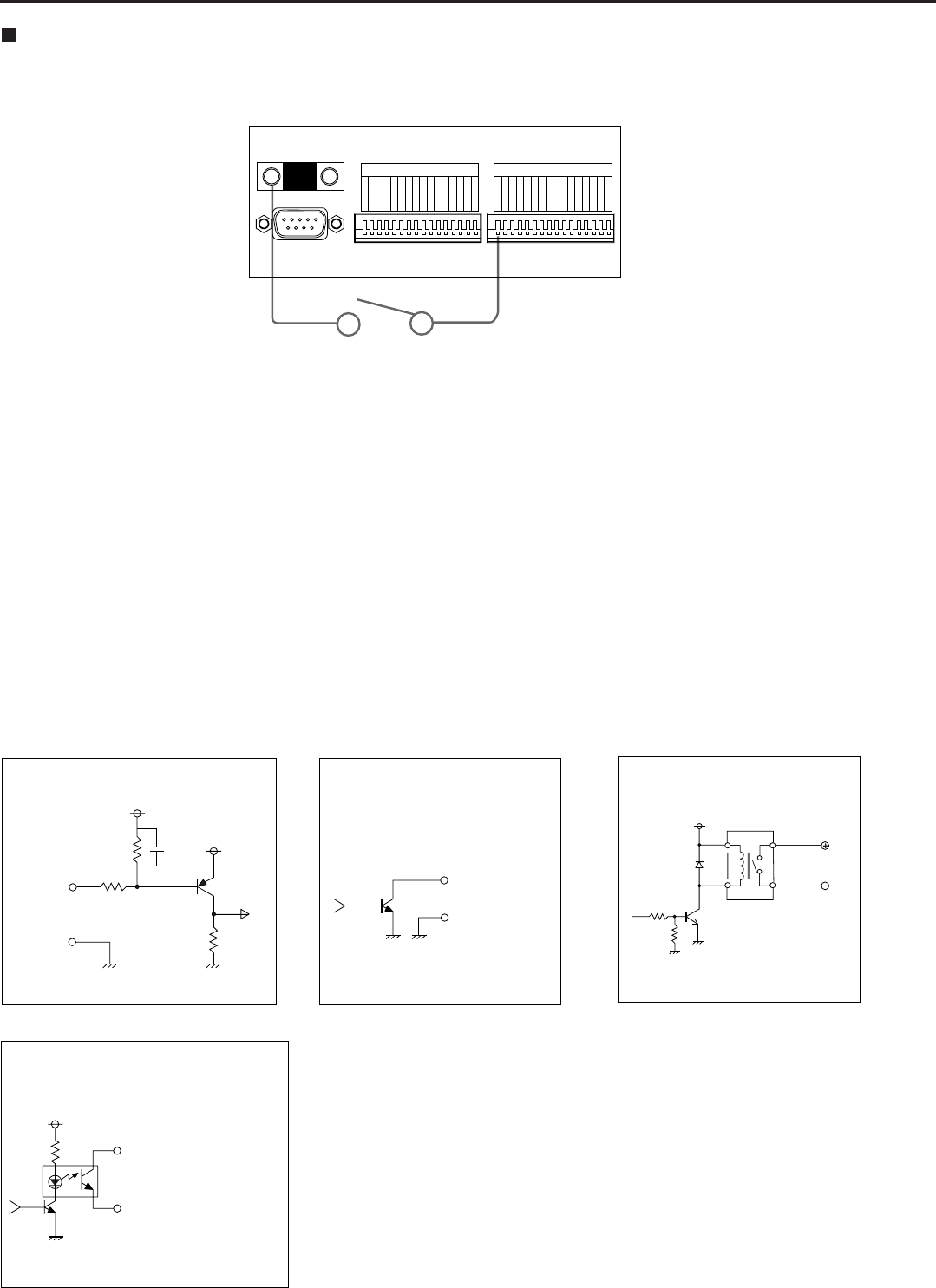
Alarm recording connection
The diagram below shows an example connection for setting alarm signal to sensor number 1.
ALARM SWITCH
RS-232C
GND
ALARM OUT
1
2
3
4
5
6
7
8
9
10
11
12
13
14
15
16
ALARM IN
1
2
3
4
5
6
7
8
9
10
11
12
13
14
15
16
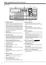
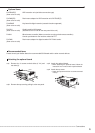
<Interface circuit inside the unit>
5V
5V
10kΩ
22kΩ
Input
terminal
0.047µF
GND
EMERGENCY/ALARM IN/REC/
CLOCK ADJ Input terminal
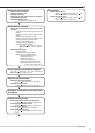
• Input Circuit
4.7kΩ
<Interface circuit inside the unit>
MODE OUT 1 - 4 Output terminal
• Output Circuit
MODE OUT
<Interface circuit inside the unit>
CALL OUT terminal
CALL OUT GND terminal
CALL OUT Output terminal
• Output Circuit
<Interface circuit inside the unit>
Output terminal
GND terminal
ALARM OUT Output terminal
• Output Circuit