


Appendix A-9
Appendix
009
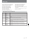
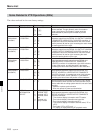
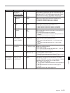
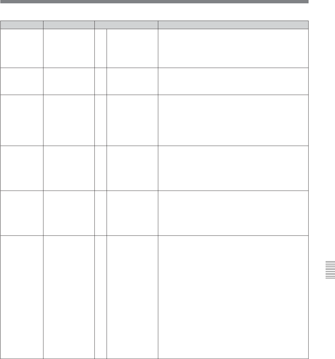
Item number Item Settable range
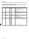
006
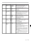
Selects which buttons on the control panel are enabled,
when this unit is in the remote control mode.
0: All switches and buttons are disabled.
1: Only the STOP and EJECT buttons are enabled.
2: All switches and buttons except the RECORDER button
and PLAYER button are enabled.
LOCAL FUNCTION
ENABLE
0
[1]
2
TAPE TIMER
DISPLAY
Determines whether the CTL counter displays a 12-hour or
24-hour clock.
0: 12-hour clock
1: 24-hour clock
[+/–12H]
24H
[0]
1
Function
007
008
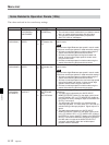
MONITORING
SELECTION FOR
VTR-TO-VTR
EDIT
In two-VTR editing system when only one monitor is
connected to the recorder, selects whether the recorder
automatically changes to E-E mode and outputs the player’s
playback signal on the monitor whenever the recorder’s
PLAYER button is pressed.
0: The recorder does not change to E-E mode.
1: The recorder change to E-E mode to and outputs the
playback signal of the player.
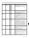
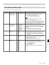
CHARACTER
TYPE
011
Determines the vertical size of superimposed characters
output from the SERIAL V/A OUTPUT 4(SUPER) or VIDEO
OUTPUT COMPOSITE 3(SUPER) connector.
01: Standard size
02: Two times standard size
03: Three times standard size
04: Four times standard size
[01]
02
03
04
CHARACTER
V-SIZE
CONDITION
[white]
black
W/out
B/out
[1]
× 2
× 3
× 4
[disable]
enable
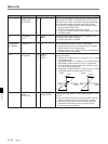
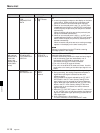
012
Determines whether or not to include the display of the
channel condition with the superimposed characters.
0: Does not display the condition.
1: Displays the condition.
How the channel condition display format:
The condition is displayed below the timer or status line of
the characters. (The entire area for displaying the condition
is blank when an analog tape is inserted.)
Example: V– – – – A– – – –
The four characters following “V” indicate the condition of
each video channel from Ach to Dch of the rotary head.
The four characters following “A” indicate the condition of
each audio channel from Ach to Dch of the rotary head.
Character pattern
(Space): The condition is not indicated on the front panel
(STBY OFF, etc.).
– : The condition is good (the green indicator lights up).
* : The condition is less than good (the yellow indicator
lights up).
p : The condition is bad (the red indicator lights up).
[0]
1
CONDITION
DISPLAY ON
VIDEO
MONITOR
Determines the type of superimposed characters output from
the SERIAL V/A OUTPUT 4(SUPER) or VIDEO OUTPUT
COMPOSITE 3(SUPER) connector.
0: White letters on a black background
1: Black letters on a white background
2: White outline letters
3: Black outline letters
[recorderonly]
auto switch
[0]
1
[0]
1
2
3
all disable
[stopeject]
all enable
×
&