


4-3 TC Menu
4-24 Chapter 4 Menu Settings
Chapter 4 Menu Settings
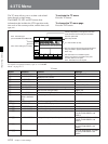
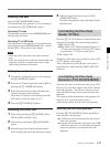
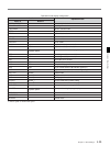
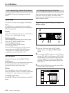
Indication Time data
CTL counter data
TCR Time data of the LTC reader
UBR User bits data of the LTC reader
TCR. The time data of the VITC reader
UBR. User bits data of the VITC reader
TCG. Time data of the time code generator
UBG User bits data of the time code generator
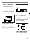
IN IN point or starting point of the DMC memory
OUT
AI AUDIO IN point
AO
DUR
AUDIO OUT point
Duration between two points edit (IN, OUT,
AUDIO IN, or AUDIO OUT) points
OUT point or the ending point of the DMC
memory
CTL
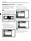
1Types of time data
Note
When a time data or user bits reading error has
occurred, an asterisk (“*”) is displayed where the error
has occurred. For example, “T*R”, “U*R”, “T*R.”, or
“U*R.”.
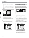
2 Drop frame mark of the time code reader
(DVW-A500/1 and 500/1 only)
“•”: Drop frame mode (factory-setting)
“:”: Non-drop frame mode
3 Drop frame mark of the time code generator
(DVW-A500/1 and 500/1 only)
“•”: Drop frame mode (factory-setting)
“:”: Non-drop frame mode
4 Field mark of the VITC data
“ ” (blank): Fields 1 and 3 are displayed.
“*”: Fields 2 and 4 are displayed.
5 Control VTR indication
When editing using two VTRs, this indication tells you
which VTR is being controlled by the control panel.
This indication does not appear when two VTRs are
not being used.
R: The VTR control panel controls the recorder VTR
(the RECORDER button on the control panel
lights up).
P: The VTR control panel controls the player VTR
(the PLAYER button on the control panel lights
up).
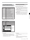
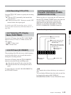
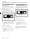
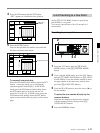
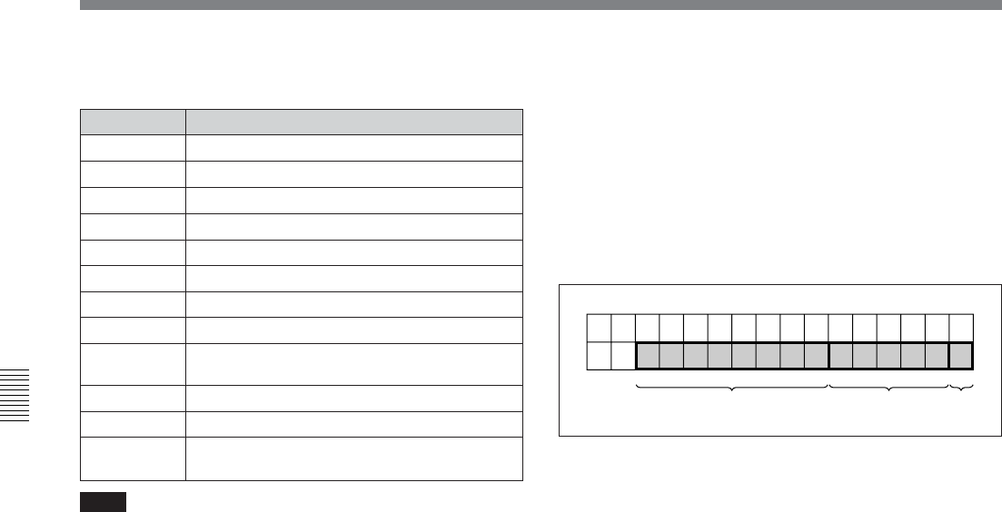
6 Operation mode
This display is divided into three blocks (A, B, and C),
as shown in the following figure.
Block A: Operation mode
Block B: Servo lock condition or tape speed
Block C: Edit segment during automatic editing, or a
p mark indicating tape speed memorization for
recording/playback in DMC mode
Operation mode
ABC