


Menu List
A-26 Appendix
Appendix
Item number Item Function
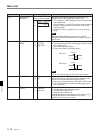
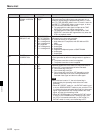
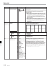
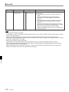
Specifies the phase rotation domain of the chroma phase
(hue) control.
The output level of SIF, component, and composite signals
are simultaneously modified in accordance with the
following modes:
0: When monitoring the composite output level of the VTR
with a composite vector monitor (Sony Tektronix 1750
for DVW-A500/1 and 500/1, and 1751 for DVW-A500P/1
and 500P/1), rotating the CHROMA PHASE (hue)
control changes only the chroma phase (hue), but not
the chroma level.
1: When monitoring the component output level of the VTR
with a component vector monitor (Sony Tektronix
WFM300A), rotating the CHROMA PHASE (hue) control
changes only the chroma phase (hue), but not the
chroma level.
U/V (composite)
domain
Pb/Pr (component)
domain
708
CHROMA PHASE
ROTATION MODE
[0]
1
Settable range
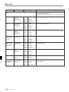
Sub item
[OFF]
100% Color Bars
75% Color Bars
75% Reverse Color
Bars
Bowtie
Pulse & Bar
Multi Burst
H Sweep
5 step
Ramp
Shallow Ramp
Red
50% Flat
100% Flat
Black Burst
SDI Check Field
Line 330
(DVW-A500P/1 and
500P/1 only)
Test singal NTC7
(DVW-A500/1 and
500/1 only)
0
1
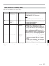
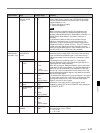
OUTPUT CAV
LEVEL
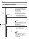
709
(DVW-A500/1
and 500/1 only)
DECODE Y/C SEP
MODE
INPUT CAV
LEVEL
[B-CAM]
D-1
[B-CAM]
D-1
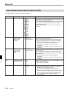
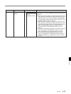
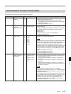
710 INTERNAL VIDEO
SIGNAL
GENERATOR
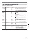
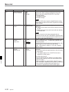
Specifies the D-1 or Betacam format as the input/output
format for analog component signals.
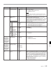
Betacam
with 100/
7.5/77/7.5
color bars
714 mV
Format
Color Bars
D-1 CAV
with 100/0/
100/0 color
bars
Y video
700 mV
Y sync
300 mV
286 mV
700 mV
700 mV
R-Y/B-Y
Analog component input format
0: Betacam format
1: D-1 format
Analog component output format
0: Betacam format
1: D-1 format
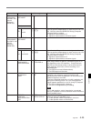
Specifies the type of test signal to be output from the
VTR’s internal test signal generator.
When OFF is selected, no test signal is output and the
VTR operates normally.
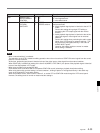
For settings other than OFF, hold down the lit AUDIO
INPUT/MONITOR SELECT button for 3 seconds or more.
All the AUDIO INPUT/MONITOR SELECT buttons light
and the internal test signal generator operates. The
selected test signal (1 through 17) is output from the VTR.
The output signal can also be recorded.
[0]
1
[0]
1
[0]
1
2
3
4
5
6
7
8
9
10
11
12
13
14
15
16
17