


Menu List
A-16 Appendix
Appendix
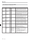
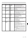
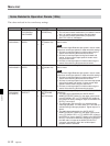
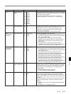
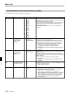
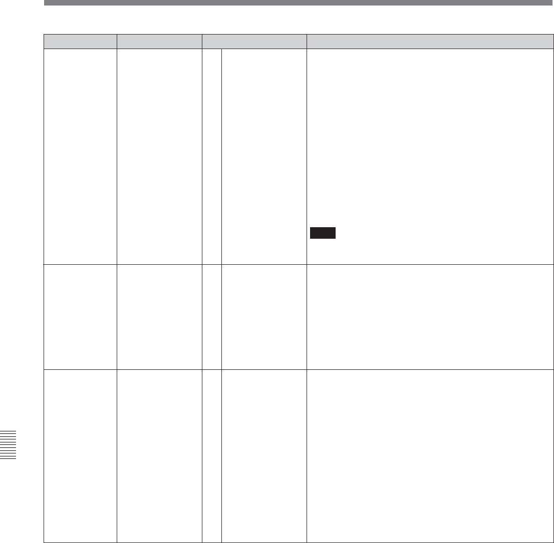
Item number Item Function
[manual]
neg & excess
neg
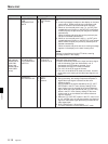
Specifies the action taken when an edit point is incorrectly
set.
0 : a warning message is output on the display on the lower
control panel. Delete manually the unnecessary edit
points or correct the erroneous edit point manually.
1 : When an incorrect edit point is set, (i.e., an OUT point
located before an IN point, or AUDIO OUT point before
AUDIO IN point) the previously set edit point is deleted
automatically.
When excessive edit points are set, the previously set
edit point is deleted automatically.
2 : When an incorrect edit point is set (i.e., an OUT point
located before an IN point, or AUDIO OUT point located
before AUDIO IN point) the previously set edit point is
deleted automatically.
When excessive edit points are set, a warning message
appears in the display on the lower control panel.
Note
Editing is not performed on the VTR while a warning
message aprears in the display.
AUTO-DELETION
FOR
INCONSISTENT
DATA
307
[0]
1
2
Settable range
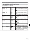
The servo reference is selected by the following settings.309
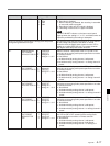
Select the STD or NON-STD signal mode according to the
composite video input signal.
0 : Detect automatically whether the input luminance signal
and chrominance signal are interleaved or not. If
interleaved, the STD mode is selected. If not
interleaved, the NON-STD mode is selected.
1 : The unit is in the STD mode at all times.
2 : The unit is in the NON-STD mode at all times. Use this
mode when color framing of the video input signal is not
stable.
SELECTION OF
STD/NON-STD
FOR COMPOSITE
VIDEO IN
[auto]
forced STD
forced non-STD
[0]
1
2
308
(with optional
BKDW-505 for
DVW-500/1
series, and
BKDW-506 for
DVW-500P/1
series)
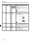
SERVO/AV
REFERENCE SEL
[0]
1
2
[auto1]
auto 2
external
0: During recording, the analog component/composite or
digital video input signal is selected as the servo
reference signal.
During playback, the signal selected by the [F2] (OUT
REF) button in the PF1 menu (factory setting) on the
lower control panel is selected as the servo reference
signal. When the signal selected by the [F2] (OUT REF)
button in the PF1 menu (factory setting) on the lower
control panel is not connected, the internal reference
signal is selected.
1: When the [F2] (OUT REF) button in the PF1 menu is set
to “ref”, and the unit is in edit preset mode, the reference
signal for video/audio signal processing is locked to the
video input signal.
2: SYS1 ROM version 1.06 and higher
The servo reference is forced into the EXT mode.