


Appendix A-39
Appendix
[0]
1
K10
Item number
Function
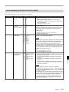
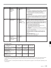
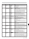
TC GENERATOR
EXT/INT
Item
[0]
1
Selects the time code generated by the internal or external
time cord generator.
0: Selects the time code generated by the internal time
code generator.
1: Selects an external time code input to the TIME CODE
IN connector.
TC GENERATOR
REGEN/PRESET
K11 [preset]
regenerate
[0]
1
Selects the time code with which the internal time code
generator synchronizes.
0: Presets the initial settings of the time code generated by
the internal time code generator with operation through
the front panel or remote control from the device
connected to the REMOTE1-IN (9P) connector.
1: The internal time code reader synchronizes with the
time code read by the internal time code reader
(regenerates the time code).
REC RUN/FREE
RUN
K12 [freerun]
rec run
[0]
1
Selects the time code running mode.
0: The time code advances when the power is on
regardless of the VTR’s operation mode.
1: The time code advances only during recording.
When selecting this setting, set the [F6] (TCG SOURCE)
button to int, the [F7] (TCG MODE) button to prst.
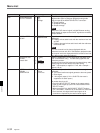
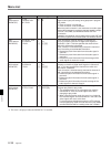
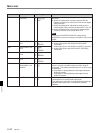
Settable range
[internal]
external
[dropframe]
non-drop frame
[0]
1
Selects the running mode for the CTL counter and the time
code generator.
0: Drop frame mode (DF is displayed.)
1: Non-drop frame mode (NDF is displayed.)
DF/NDF
K13
(DVW-A500/1
and 500/1 only)
[on]
off
[0]
1
Specifies the recording of VITC.
0: Records VITC generated by the internal time code
generator.
1: Does not record VITC. However, records VITC inserted
in the video input signal.
For details on the VITC insertion line, refer to “4-3-10
Setting the VITC Insertion Line (VITC POS-1/POS-2)” on
page 4-26.
VITCK14
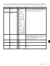
[off]
on
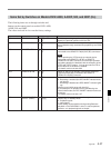
ID PRESET
K15
The presetting of the ID code in non-volatile memory as
user bits data enables recalling and record it during later
recording sessions.
0: Records the user bits set through the control panel.
1: Records the preset ID code as user bits data.
For details on presetting ID code, refer to the item 603.
off
[on]
0
[1]
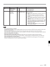
SUPERIMPOSED
CHARACTER
K16
Set to on to superimpose time data and operation mode
indicated as character data onto the signals output from the
SERIAL V/A OUTPUT 4(SUPER) and VIDEO OUTPUT
COMPOSITE 3(SUPER) connectors.
0: Does not superimpose time data and operation mode.
1: Superimposes time data and operation mode.
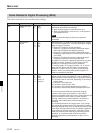
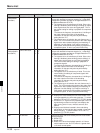
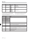
VIDEO INPUT
SELECT
K17 [sif]
composite
component(y-t/b)
[0]
1
2
Selects the video input signal.
0: The serial digital video signal input to the SERIAL V/A
INPUT connector.
1: The analog composite video signal input to the
COMPOSITE VIDEO INPUT connector.
2: The analog component video signal input to the
COMPONENT VIDEO INPUT connectors.
OUTPUT
REFERENCE
SELECT
K18
ref.video
input video
[0]
1
Selects the signal to be used as the reference signal for
VTR operations.
0: The signal input to the REF.VIDEO connector is used as
the reference signal for playback and audio recording.
Digital audio and video input signals must synchronize
with this reference signal during recording.
1: The video input signal is used as the reference signal for
VTR operations. The [F1] (VIDEO IN) button in the PF1
menu (factory setting)switches the video input signal.