


Chapter 2 Locations and Functions of Parts and Controls 2-15
Chapter 2 Locations and Functions of Parts and Controls
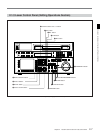
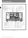
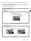
1 COMPOSITE VIDEO OUTPUT connectors
(BNC)
Output analog composite video signals. The signal
output to connector 3(SUPER) contains superimposed
characters for time data or menu settings when on is
selected with the ALT button and [F6] (CHARA
SUPER) button in the TC menu.
2 COMPONENT VIDEO INPUT connectors
(BNC)
Accept analog component video signals (Y/R-Y/B-Y).
3 COMPOSITE VIDEO INPUT connectors
(BNC) and 75Ω termination switch (with
optional BKDW-505 for DVW-A500/1 and 500/
1, or BKDW-506 for DVW-A500P/1 and 500P/1)
Accepts analog composite video signal.
Set the 75Ω termination switch to OFF when this VTR
is bridge-connected. Otherwise, set it to ON.
4 REF.VIDEO INPUT connectors (BNC) and 75Ω
termination switch
One of these connectors accepts a reference video
signal. Use a video signal with chroma burst (BVS) or
a black and white video signal (VS) as a reference
video signal.
When making a bridge connection with a loop-through
output, set the 75Ω termination switch to OFF.
Otherwise, set it to ON.
5 BREAKER button
Disconnects the primary circuit of the AC power
transformer should an excessive current be detected.
6 AC IN connector
Connects to an AC outlet using the power cord
supplied with the VTR.
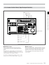
7 COMPONENT VIDEO OUTPUT connectors
(BNC)
Output analog component video signals (Y/R-Y/B-Y).
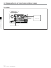
8 SERIAL V/A (video/audio) OUTPUT connectors
(BNC)
Output up to four (1 to 4) serial digital video/audio
signal lines. The signal output to connector 4(SUPER)
contains superimposed characters for time data or
menu settings when on is selected with the ALT button
and [F6] (CHARA SUPER) button in the TC menu.
9 SERIAL V/A (video/audio) INPUT connectors
(BNC)
The left connector accepts serial digital video/audio
signals. When the VTR is powered on, the right
connector serves as an active loop-through output to
allow a bridge connection.
0 AUDIO INPUT (AES/EBU) connectors
(XLR-3-31)
Accept up to two lines (four channels: channels 1/2
and channels 3/4) of AES/EBU format digital audio
signals.
!¡ AUDIO INPUT LEVEL/600Ω termination
switches
Set according to the audio input level of each channel
input to the ANALOG AUDIO INPUT connectors and
the audio input impedance.
LOW with OFF:
Audio input level: –60 dBu (microphone input)
Audio input impedance: High (about 20 kΩ)
HIGH with OFF:
Audio input level: +4 dBu (line input)
Audio input impedance: High (about 20 kΩ)
HIGH with ON:
Audio input level: +4 dBm (line input)
Audio impedance: 600 Ω
!™ ANALOG AUDIO INPUT connectors
(XLR-3-32)
Accept up to five analog audio signal lines (channels 1
to 4 and cue).
!£ ANALOG AUDIO OUTPUT connectors
(XLR-3-31)
Output up to five analog audio signal lines (channels 1
to 4 and cue).
!¢ CONTROL PANEL connector (15-pin)
Connects the control panel through the 15-pin cable
supplied with the optional BKDW-510 Control Panel
Extension Kit when using the control panel as a remote
controller.