


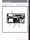
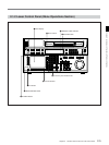
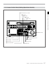

2-1 Control Panel
2-6 Chapter 2 Locations and Functions of Parts and Controls
Chapter 2 Locations and Functions of Parts and Controls
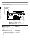
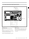
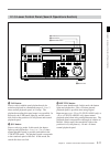
1 Menu display
Menus selected by pressing the menu buttons appear
here.
Each menu shows the functions assigned to each
function button ([F1] to [F10]) and information
necessary for making settings, such as time codes.
2 Menu buttons
Press to activate the respective menu.
HOME button: Activates the HOME menu.
Settings for basic or editing operations are made
in the HOME menu.
TC button: Activates the TC (time code) menu. In
the TC menu, you can switch between LTC and
VITC and between DF and NDF (DVW-A500/1
and DVW-500/1 only), and make settings for time
code displays on an external monitor.
CUE button: Activates the CUE menu. In the CUE
menu, you can register 10 cue points per page for
a total of 100 cue points.
PF1 button: Activates the PF (Personal Function) 1
menu. In the PF1 menu, you can register
frequently used settings in other menus. Settings
for video input/output signals are factory set.
PF2 button: Activates the PF (Personal Function) 2
menu. In the PF2 menu, you can register
frequently used settings in other menus. Settings
for audio input/output signals are factory set.
SET UP button: Activates the SET UP menu. Use
the SET UP menu to restore settings to the VTR
memory banks or IC memory card, register
functions to the PF1/2 menus, and set items in the
VTR SETUP menu.
For details, refer to “Chapter 4 Menu Settings” on page 4-
1.
3 MEMORY CARD indicator
Lights up when the IC memory card is inserted.
4 ACCESS button
Press this button to directly activate the MEMORY
CARD menu. Flashes when the control panel is
accessing the IC memory card.
Note
Do not eject the IC memory card while the ACCESS
button lights up as this may damage the contents of the
memory card.
5 IC memory card insertion slot
Insert IC memory cards here. VTR settings can be
stored on cards and used to configure the VTR and
control panel at a later date, thus reducing the time
required for set up.
Press the button beside the insertion slot to eject the IC
memory card.
6 Function buttons
Activate the functions for the respective function
buttons in each menu.
7 ALT (alternative) button
Press to change the functions of the current menu.
Press again to return to the original functions.
8 MAINTENANCE switch
Activates the MAINTENANCE menu.
To operate this switch, push it in using the tip of a pen
or some other pointed object while holding down the
SFT button.
9 ALARM indicator
Lights up when the communication between the VTR
and the control panel is abnormal.