


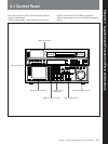
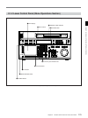
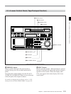

2-1 Control Panel
2-4 Chapter 2 Locations and Functions of Parts and Controls
Chapter 2 Locations and Functions of Parts and Controls
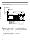
!º INPUT SELECT button
Selects the audio input signal. Press to light the button
up, then press one of the AUDIO INPUT/MONITOR
SELECT buttons to select the type and the channel of
the audio signal.
SIF (CH-1 to CH-4): Selects signal input to the
SERIAL V/A INPUT connector.
AES/EBU (CH-1 to CH-4): Selects signal input to
the AUDIO INPUT (AES/EBU) connectors.
ANALOG (CH-1 to CH-4): Selects signal input to
the ANALOG AUDIO INPUT connectors.
If you select the SERIAL V/A INPUT or AUDIO
INPUT (AES/EBU) connectors when there is no
incoming signal, the INPUT SELECT button flashes.
This specification can also be done as a menu
operation.
For details, refer to “4-6-1 Selecting the Audio Input Signal
(A-IN ALL to A-IN CH4)” on page 4-37.
!¡ AUDIO INPUT/MONITOR SELECT buttons
Select the audio input signal when the INPUT
SELECT button lights up, or the audio signal to be
monitored when the MONITOR SELECT button lights
up.
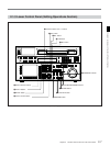
!™ VIDEO INPUT SELECT buttons
Press one of the following buttons to select the video
input signal.
If you select a connector which has no incoming
signal, the button flashes.
SIF: Selects the serial digital video signal input to
the SERIAL V/A INPUT connector.
COMPONENT (Y-R, B): Selects the analog
component video signal input to the
COMPONENT VIDEO INPUT connectors.
COMPOSITE: Selects the analog composite video
signal input to the COMPOSITE VIDEO INPUT
connector.
Note
To input analog composite video signal, you must
install the optional BKDW-505 (for NTSC video
format)/BKDW-506 (for PAL video format) Analog
Composite Decoder Board.
!£ REMOTE buttons and RS-232C indicator
Press these buttons to select external equipment to be
used to remotely control the VTR.
1(9P): Press to select the unit connected to the
REMOTE1-IN(9P)/OUT(9P) connectors. The
button lights up.
2(50P): Press to select the unit connected to the
REMOTE PARALLEL I/O(50P) connector (with
optional BKDW-509). The button lights up.
RS-232C indicator: Lights up when the VTR is
communicating with the external equipment
connected to the RS-232C connector.
Note
When the VTR is being controlled by external
equipment connected to the REMOTE1-IN(9P) or
REMOTE PARALLEL I/O(50P) connector, all tape
transport buttons and edit operation buttons are
disabled, except the STOP and EJECT buttons. You
may also specify the disabling or enabling of all
buttons by setting 006. LOCAL FUNCTION
ENABLE in the VTR SETUP menu.