


Chapter 4 Menu Settings 4-35
Chapter 4 Menu Settings
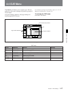
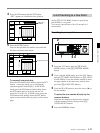
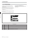
Adjusting the output level
Make this adjustment with the [F4] (VIDEO GAIN)
button.
prst: Selects the standard setting.
Numerical value: 0 to B50H
Adjustable range: –3 to +3 (dB)
The range of the numerical value may be adjusted
through 714. VIDEO ADJUST RANGE of the VTR
SETUP menu. The range is ±3 dB when controlling
the VTR from a device (such as a BVR-50) connected
to the VIDEO CONTROL connector in the connector
panel.
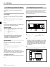
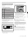
Adjusting the chroma output level
Make this adjustment with the [F5] (CHROMA GAIN)
button.
prst: Selects the standard setting.
Numerical value: 0 to B50H
Adjustable range: –3 to +3 (dB)
The range of the numerical value may be adjusted
through 716. CHROMA GAIN of the VTR SETUP
menu. The range is ±3 dB when controlling the VTR
from a device (such as a BVR-50) connected to the
VIDEO CONTROL connector in the connector panel.
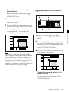
Adjusting the setup level/black level
DVW-A500/1 and 500/1 only
Adjust the setup level with the [F6] (SETUP LEVEL)
button.
prst: Selects the standard setting.
Numerical value: 0 to 220H
Adjustable range: –30 to +30 (IRE)
DVW-A500P/1 and 500P/1 only
Adjust the black level with the [F6] (BLACK LEVEL)
button.
prst: Selects the standard setting.
Numerical value: 0 to 220H
Adjustable range: –210 to +210 (mV)
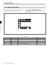
Adjusting the Y/C delay during analog
Betacam playback (DVW-A500/1 series
only)
Make this adjustment with the [F7] (Y/C DELAY)
button.
prst: Selects the standard setting.
Numerical value: 0 to FFFH
Adjustable range: –100 to +100 (ns)
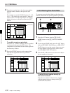
Adjusting the chroma phase
Set the hue (the relative phase between burst and
chroma) with the [F8] (CHROMA PHASE) button.
prst: Selects the standard setting.
Numerical value: 0 to FFH
Adjustable range: –30 to +30 ( ˚ )
Adjusting the system synchronization
phase
Make this adjustment to match the output phase of the
VTR precisely to that of the reference signal, or to
create special effects as fading, wrapping, and
dissolving through connection with a switcher, and in
conjunction with other VTRs.
The [F9] (SYSTEM SYNC) button sets the sync phase
of the output signal relative to the reference signal
input to the VTR.
prst: Selects the standard setting.
Numerical value: 0 to FFH
Adjustable range: –15 to +15 (µs)
Adjusting the system sub-carrier phase
Make this adjustment to precisely match the output
phase of the VTR relative to the phase of the reference
signal with the level of the sub-carrier phase during
editing using composite signals. This adjustment
keeps the SCH (Sub-Carrier Sync) phase of the output
constant.
The [F10] (SYSTEM SC) button sets the sync and sub-
carrier phases of the output signal relative to the
reference signal input to the VTR.
prst: Selects the standard setting.
Numerical value: 0 to 3FFH
Adjustable range: –200 to +200 (ns)