


Chapter 2 Locations and Functions of Parts and Controls 2-3
Chapter 2 Locations and Functions of Parts and Controls
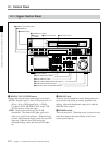
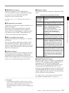
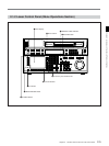
8 Indicator window
The following indicators light up to indicate the VTR’s
status.
Indicator Status
Lights up when the Dolby NR circuit is
activated.
DOLBY NR
(DVW-A500/1
series only)
Indicators and corresponding VTR status
KEY INHIBIT Lights up when the [F1] (KEYINH) button
in the PANEL SETUP menu is set to on.
CHANNEL
CONDITION
Indicates the playback signal condition.
Green: Playback signal is good.
Yellow: Playback signal is less than
good, but still reproducible.
Red: Playback signal is poor. Head
cleaning or internal inspection is
necessary if the indicator lights up
continuously.
DIGITAL Lights up when a Digital Betacam
cassette is inserted, and turns off when
an analog Betacam cassette is inserted.
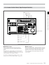
4 PHONES level control
Adjusts the output level to the PHONES jack.
You can enable this control to simultaneously adjust
the output level to the MONITOR OUTPUT
connectors on the connector panel.
For details, refer to “5-1-2 Selecting Audio Signals” on
page 5-2.
5 PB (playback) level controls
Adjust the level of the audio output for channels 1 to 4
and the cue channel.
Pull out the controls during playback to adjust the
audio output for each channel. Push in again for
factory-set levels (+4 dB output for a signal recorded
at a reference level of 0 dB). When pushed in, the
controls cannot adjust the audio output level.
6 REC (recording) level controls
Adjust the recording level for channels 1 to 4 and the
cue channel.
Pull out the controls to adjust the recording level for
each channel in E-E mode
1)
. Push in again for the
factory-set recording level (0 dB reference level for an
input of +4 dB). When pushed in, the controls cannot
adjust the recording level.
7 Audio level meters
Indicate the recording level in recording or E-E mode
or the playback level in playback or CONFI mode.
The display range can be changed by pressing the
DISPLAY FULL/FINE button. The reference level is
factory set at –20 dB, and the peak level at 0 dB.
LTC Lights up when the VTR is recording LTC
signals or reading LTC signals during
playback. Also lights up in E-E mode if
you press the REC button while the [F6]
(TCG SOURCE) button in the TC menu
set to ext, allowing you to verify that the
VTR is locked to an external time code.
VITC Lights up when the VTR is reading VITC
signals during playback, or when the VTR
is in recording or E-E mode and the video
input signal contains VITC signals. Also
lights up when the [F10] (VITC) button in
the TC menu is set to on and the VITC
signals contained in the video signal are
normal.
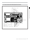
9 MONITOR SELECT button
Selects the audio signal to be output at the MONITOR
OUTPUT L/R connector(s). Press to light the button
up, then press the AUDIO INPUT/MONITOR
SELECT button(s) to specify which channel(s) are to
be monitored at the MONITOR OUTPUT L or R
connector. If you specify more than one channel to the
same MONITOR OUTPUT connector, a mixed audio
signal is output from that connector. This specification
can also be done as a menu operation.
For details, refer to “4-6-4 Selecting the Monitor Output
Signal (MON-L SEL/MON-R SEL)” on page 4-37.
1) E-E mode
An abbreviation for Electric-to-Electric mode. In this
mode, video or audio input signals are passed and output
only through the VTR’s internal circuitry, and not
through the magnetic conversion system comprising tape
and heads.
..........................................................................................................................................................................................................