


3-2 Reference Signals for Video Output and Servo System
3-4 Chapter 3 Setting Up the VTR
Chapter 3 Setting Up the VTR
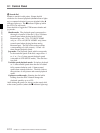
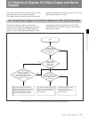
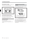
3-2-2 Reference Signal for the Servo System
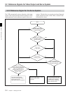
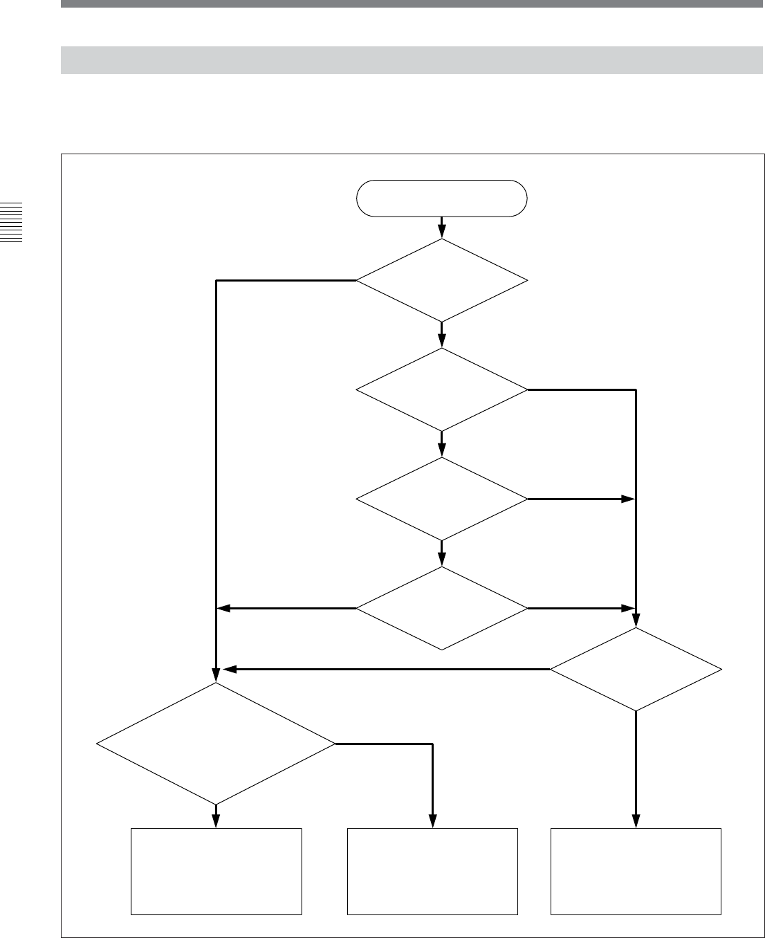
Automatic selection of reference signal for the servo system
system. Which of the two signals is selected depends
on the operational status of the VTR, as shown in the
following flow chart.
The VTR automatically selects either the video input
signal or the output from the internal reference video
signal generator as the reference signal for the servo
Start
ref
No
Setting of the [F6]
(TCG SOURCE) button
in the TC menu?
ext
No
No
Yes
Yes
input
Is the VTR
in edit mode?
Is the VTR in
recording mode?
Is a signal being
input to the video input
connector selected?
Yes
No
Is a signal being input
to the connector selected by
either the VIDEO INPUT
SELECT button or the [F1]
(VIDEO IN) button in
the PF1 menu?
The servo locks with the
reference video signal being
input to either of the
REF.VIDEO INPUT connectors.
The servo locks with the internal
reference video signal
generator.
The servo locks with the video
input signal selected by either
the VIDEO INPUT SELECT
button or the [F1] (VIDEO IN)
button in the PF1 menu.
Yes
int
Setting of the [F2]
(OUT REF) button in
the PF1 menu?