


RS-232C Interface
118
• DOWN (63H) [JVC-1]
• RIGHT (64H) [JVC-1]
• LEFT (68H) [JVC-1]
• UP (69H) [JVC-1]
Shifts the parameter settings when the timer PRG and the
alarm search parameters have been set.
Shifts the selection fields with the [UP] and [DOWN] keys
when the menu is being displayed.
• Vol +, – (65H, 66H) [JVC-1]
Changes the set values with + (ascending) and –
(descending).
• SEQ (6AH) [JVC-1]
Changes the monitor output screen mode.
• MENU ON (6BH) [JVC-1]
Displays the menu.
• MENU OFF (6CH) [JVC-1]
Clears the menu.
• MENU ON/OFF (6CH) [JVC-1]
Switches between menu displays/clear.
• ON SCREEN SELECT (74H) [JVC-1]
Switches the contents displayed on screen (REMAIN
display is not performed when loop recording is set at ON.)
• CANCEL (76H) [JVC-1]
Cancels the program data on the program timer setup
screen.
• HDR PB CAMERA SET (86H) [JVC-1]
Specifies the playback camera. The monitor output camera
is specified during recording.
* FULL size sequential display, 4-screen sequential
display and 6-screen specification are invalidated when
in the playback mode (include when recording and
playback are performed at the same time.)
* The FULL size sequential display ⇔ 4-screen
sequential display specifications are invalid.
* Invalid with Second Byte: FULL size sequential display,
4-screen sequential display, 6-screen screen and 9-
screen specifications.
• DATE SET(8EH) [BASIC/JVC-1]
Sets the month, day and year in the VR-509E.
(Cannot be set when the NTP Client function is enabled, or
when the VR-509E is in the recording mode.)
• TIME SET(8FH) [BASIC/JVC-1]
Sets the hours, minutes and seconds in the VR-509E.
(Cannot be set when the NTP Client function is enabled, or
when the VR-509E is in the recording mode.)
• MENU RESET (EFH) [JVC-1]
Initializes the menu setup values.
(Cannot be set when the VR-509E is in the recording
mode, or when the operation lock has been activated.)
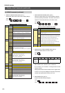
3. Details of the Commands (continued)
3.3. Setup Commands
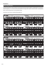
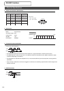
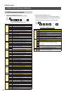
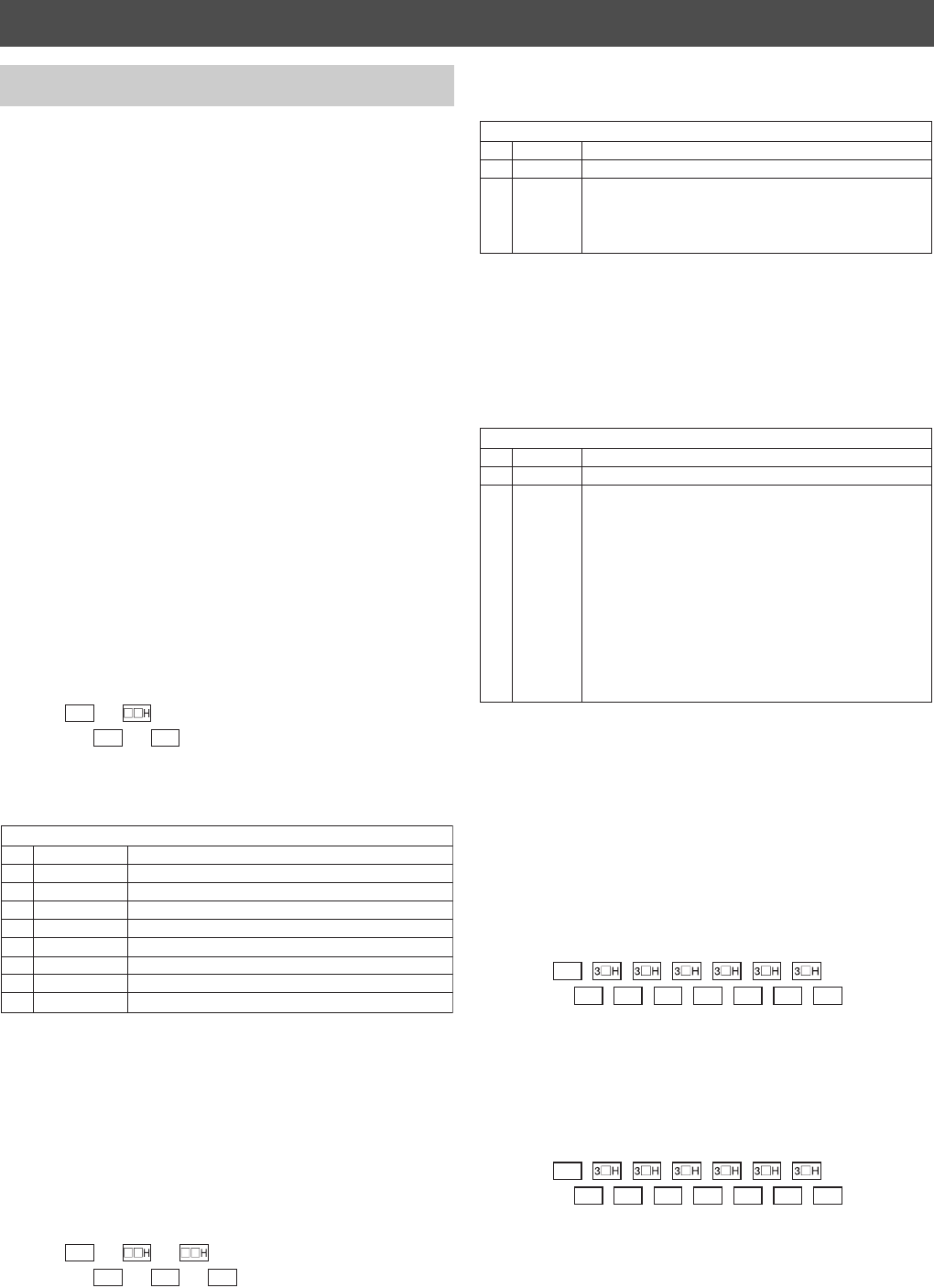
74H
1st byte 2nd byte
0AH
TXD
RXD
0AH
Second byte
Bit Status Detail
7 1 / 0 Stop recording notification : 1( ON ) / 0( OFF )
6 1 / 0 Warning display : 1( ON ) / 0( OFF )
5 1 / 0 Camera title display : 1( ON ) / 0( OFF )
4 1 / 0 Mode display : 1( ON ) / 0( OFF )
3 1 / 0 Remaining capacity display : 1( ON ) / 0( OFF )
2 1 / 0 Alarm detection display : 1( ON ) / 0( OFF )
1 1 / 0 Alarm count display : 1( ON ) / 0( OFF )
0 1 / 0 Date/time display : 1( ON ) / 0( OFF )
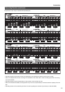
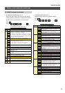
86H
1st byte 2nd byte
0AH
TXD
RXD
0AH
3rd byte
0AH
Second byte
Bit Status Detail
7 to 4
Fixed at “3”
0 / 1 / 2
3 to 0
3 / 4 / 5
6
0: FULL size specification / 1: FULL size sequential display
2: 4-screen specification / 3: 4-screen sequential display
5: 6-screen specification / 6: 9-screen specification
Third byte
Bit Status Detail
7 to 4
Fixed at “3”
3 to 0
8 to 0
Second BYTEF: During FULL size specification
8: Camera 9 specification to 0: Camera 1 specification
Second BYTEF: During 4-screen specification
2: Pattern C
1: Pattern B
0: Pattern A
Values that do not correspond to each setting are
invalidated.
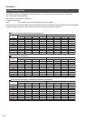
8EH
0AH
TXD
RXD
0AH
Month Day Year
0AH 0AH 0AH 0AH 0AH
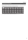
8FH
0AH
TXD
RXD
0AH
Hours Minutes Seconds
0AH 0AH 0AH 0AH 0AH