Viewing Live Camera Images
22
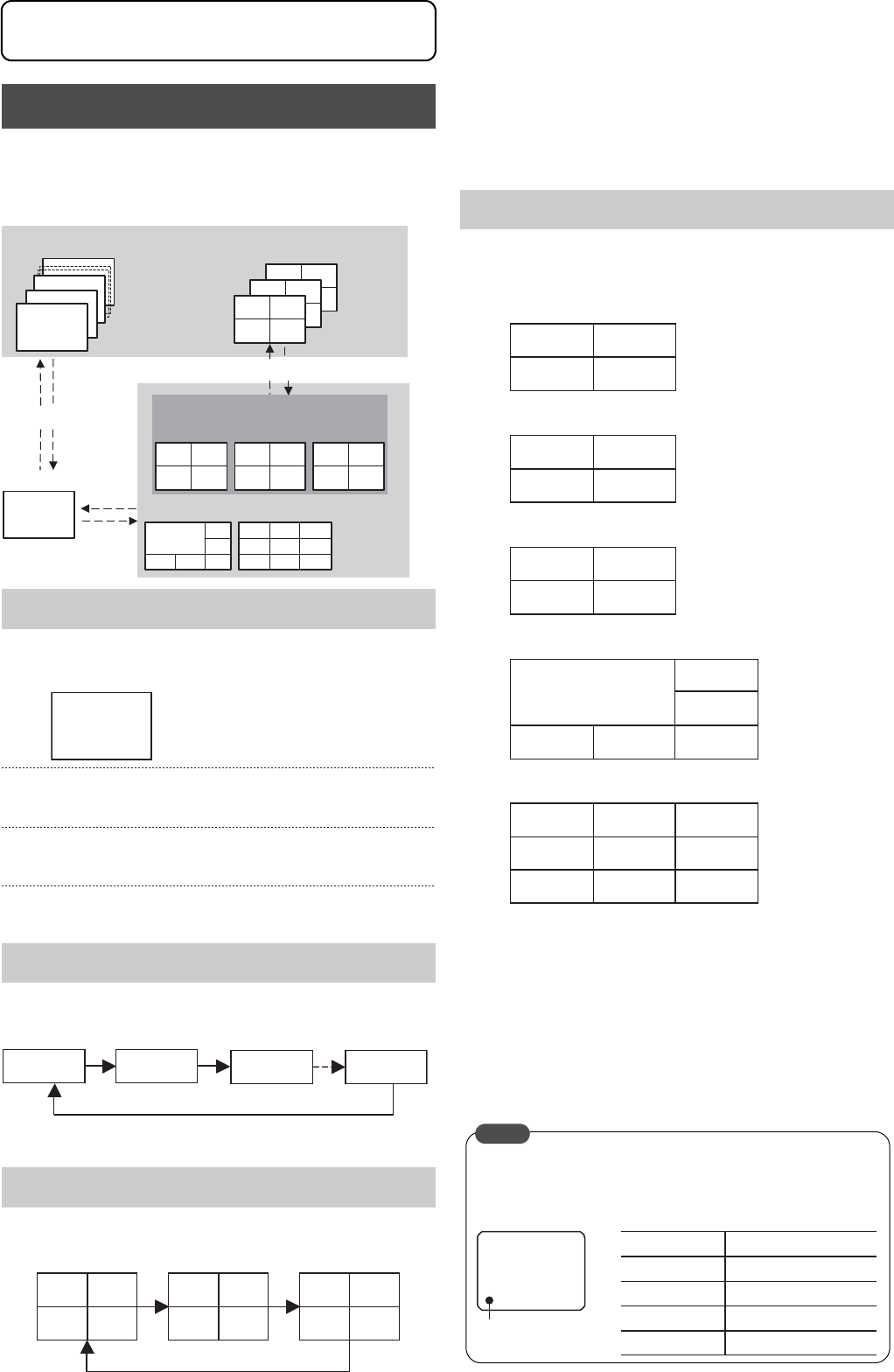
The VR-509 enables images to be viewed on single screens,
split screens, and sequential screens.
* It is not possible to change the sequential display when the
playback screen is being displayed.
• The SPLIT display LED and the SEQUENCE display LED
are both extinguished.
Press buttons [1] to [9] to switch to the required camera
input.
Press the [SPLIT] button to divide the screen into 9 split
screens.
Press the [SEQUENCE] button to activate the automatic
single screen.
• The SPLIT display LED will be extinguished and the
SEQUENCE display LED will be illuminated.
Press the [SEQUENCE] button to display the single
screen.
• The SPLIT display LED and the SEQUENCE display LED
will be both illuminated.
Press the [SEQUENCE] button to display the 4
DIVISION screen.
• The SPLIT display LED will be illuminated, and the
SEQUENCE display LED will be extinguished.
1. Press [1] to display the 4 DIV PATTERN A screen.
2. Press [2] to display the 4 DIV PATTERN B screen.
3. Press [3] to display the 4 DIV PATTERN C screen.
4. Press [4] to display the 6 DIV PATTERN screen.
5. Press [5] to display the 9 DIV PATTERN screen.
* The screen layout for the split screens are set on the “LIVE
PICTURE” screen. (Page 23)
* The position of the border will differ slightly with live images
and playback images.
Press the [SPLIT] button to display the single screen.
Press the [SEQUENCE] button to activate QUAD
PICTURE. (Possible only when the 4 DIV screen is
being displayed.)
* Sequential displays are not possible from 6 DIV and 9 DIV
displays.
Switching between Display Screens
Single Screen
Automatic Single Screen
QUAD PICTURE
CH
3
CH
7
CH9
CH3
CH2
CH1
[SEQUENTIAL]
[SEQUENTIAL]
Automatic Single
Screen Switching
QUAD PICTURE
CH9
CH5 CH6
8
CH1 CH2
CH3 CH4
[4]
[1]
[5]
CH5
[9]
[3][2]
[1]
-
CH1-9
Single Screen
SPLIT SCREEN
[SPLIT]
[SPLIT]
CH1
CH2
CH3 CH4
CH5 CH6
CH7 CH8
CH9
4 DIVISION SCREEN
CH1
CH4
CH3
CH6
CH9
CH2
CH5
CH8
CH1
CH4
CH7
CH2
CH3
CH6
CAMERA 1
CAM 1 CAM 2 CAM 3 CAM 9
CH1 CH2 CH5 CH6 CH9
CH3 CH4 CH7
CH8
SPLIT Screen
CAM 1 CAM 2
CAM 3 CAM 4
CAM 5 CAM 6
CAM 7 CAM 8
CAM 9
CAM 6
CAM 2
CAM 4 CAM 5
CAM 1
CAM 3
CAM 3CAM 1 CAM 2
CAM 8 CAM 9
CAM 4 CAM 5 CAM 6
CAM 7
Marker color
Marker
Status of the VR-900E
Blue Not recording
Red Normal recording
Yellow
Alarm recording
White
Video loss
A marker that indicates the operational status of the VR-509
is displayed at the bottom left-hand side of the screen when
the [live] screen is being displayed. (The position of the
display cannot be changed.)
MEMO
Viewing Live Camera Images


